IO-151
7
GMPN080
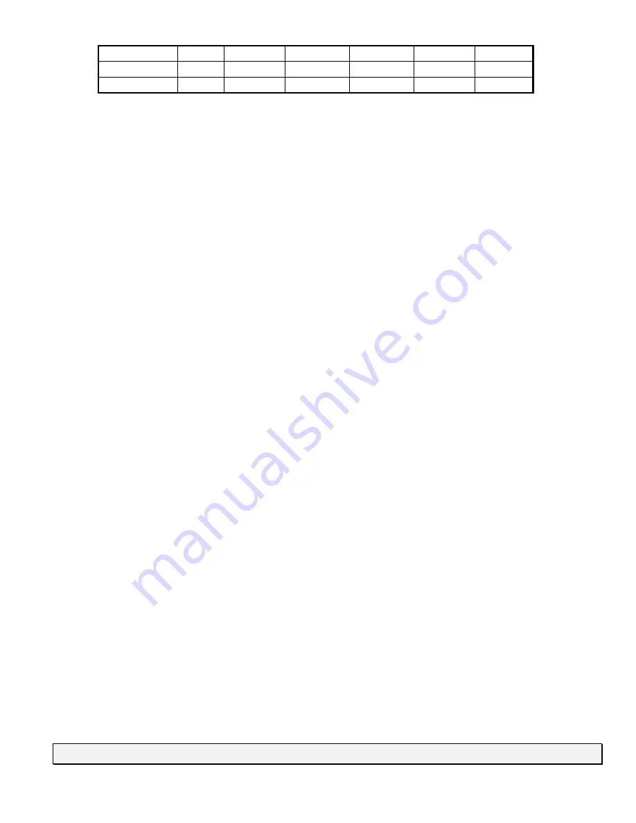
2”
75’
67.5’
60’
52.5’
45’
GMPN100
3”
100’
100’
100’
100’
100’
GMPN120
3”
100’
100’
100’
100’
100’
Should more elbows be required, subtract 7.5’ from the vent length for each elbow used (over 4
as noted above). A maximum of 6 elbows is acceptable. The use of two 45
o
over one 90
o
is
preferred. Do not count the termination as an elbow.
Minimum vent lengths are 5 ft. for vertical runs and 3ft. for horizontal runs.
A pitch of 1/4” per foot toward the drain assembly is necessary for proper drainage.
The GMPN series of gas furnace is a condensing type appliance. The products of combustion are
recirculated through a secondary coil. During this process the flue products are brought to a
temperature below dew point. Thus the moisture present in the flue products condense, leaving a
liquid by-product. This by-product must be removed from the furnace and it’s collection system.
In addition, the vent temperatures are also considerably lower than conventional furnaces. This
allows the use of low temperature plastic as the vent system. The recommended material is
schedule 40 PVC, DWV, ABS (or equivalent if allowed by local code). See previous chart for
proper sizing. The drain trap and related parts must be installed as shown in the illustrations
located elsewhere in these instructions. Failure to follow these instructions can cause products of
combustion including
Carbon Monoxide
to enter the building. This appliance may be horizontally
vented through an exterior wall. See the illustrations located elsewhere in this manual.
IF THIS FURNACE IS INSTALLED IN AN ATTIC OR SIMILAR AREA WHERE CONDENSATE
OVERFLOW MAY BE A PROBLEM AN AUXILIARY DRAIN PAN MUST BE INSTALLED
UNDER THE FURNACE WITH THE AUXILIARY DRAIN LINES ROUTED TO THE OUTDOORS
TO PREVENT WATER DAMAGE CAUSED BY LEAKS.
The vent pipes must be inspected annually.
Visually check the vent terminal screen and clean if necessary.
Visually check for blockage of the condensate disposal system. Hoses may be disconnected to
determine that proper flow is maintained. Should an obstruction be observed, it can be dislodged
by forcing a stream of water through it using a device such as a garden hose.
This appliance may be vertically or horizontally vented. Horizontal venting requires a 90
o
long
sweep elbow be installed as the vent terminal. This elbow is to be installed discharging
downward and the factory supplied termination screen is to be attached. To prevent damage to
the vent pipe and its terminal the distance from the terminal to the exiting wall is to be the
minimum practical distance (within 12” would be acceptable). Vertical venting does not require
any terminal. If desired, the vent may be faced downward to prevent water or other foreign objects
from entering the vent pipe. In that case two long radius elbows may be employed, facing
downward and terminating no less than one foot (1’) from the roof surface.
PROTECTION FROM FREEZING
The vent pipe and drain assembly must be properly protected from freezing particularly if it is
installed in an UNHEATED SPACE. Low wattage tape heaters should be employed on the drain
system. The vent pipe should be insulated using a one (1) inch thick closed foam insulation if
exposed to the outdoors. For pipes located indoors or protected from the elements such as a
garage, basement, etc. fiberglass with an R value of 7 or greater is acceptable.
CAUTION


