TEMPLATE
13-1/8
16-1/2
USE THIS INSTRUCTION
SHEET AS A TEMPLATE.
Width of cutout (13-1/8") is equal to the
width of this sheet.
Length of cutout (16-1/2") is equal to the
length of this sheet.
No. 000-0752-077 • Rev 5/05 HBP
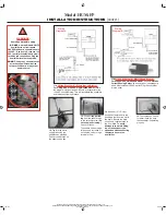
Installation Instructions and Mounting Template for
Model
HUM-FP
+LJK&DSDFLW\)DQ3RZHUHG)XPLGLÀHU
WARNING:
7KLVSURGXFWPXVWEHLQVWDOOHGE\DTXDOLÀHGKHDWLQJDQGDLUFRQGLWLRQLQJFRQWUDFWRU
.
)DLOXUHWRFRPSO\FRXOGUHVXOWLQVHULRXVLQMXU\IURPHOHFWULFDOVKRFNRUGDPDJHWRKXPLGLÀHURUKHDWLQJDSSOLDQFH
or void all warranties.
ADDITIONAL WARNINGS:
1. Disconnect electrical power
to the furnace before starting installation to avoid serious injury or electrocution.
2. Use care when cutting plenum openings and handling ductwork.
Sharp edges
m
ay cause serious injury.
3. Do not cut or drill any air conditioning or electrical accessories
during installation. Electrocution is possible if you
come in contact with a live electrical wire. Blindnes can occur if refrigerant contacts your eyes.
CAUTIONS:
1. Do not install the unit where freezing temperatures could occur, or where temperatures
could exceed 180ºF.
2. Do not install the unit on a furnace jacket.
3. Do not install the unit on a plenum face where the blanked-off ends of the cooling coil
UHVWULFWDLUPRYHPHQWWKURXJKWKHKXPLGLÀHU
4. Do not set humidity higher than recommended. Condensation damages may result.
5. Do not set humidity up to recommended levels if there is condensation on the inside
windows of any living space. Condensaion damage may result.
6. Do not install the unit on any plenum where static pressure exceeds 0.4" W.C.
7. Do not install the unit where water pressure exceeds 125 psi. Leakage may result.
%HVXUHWKDWWKHLQVWDOODWLRQZLULQJDQGSOXPELQJRQWKHKXPLGLÀHUUFRPSO\ZLWKORFDO
codes, ordinances and regulations.
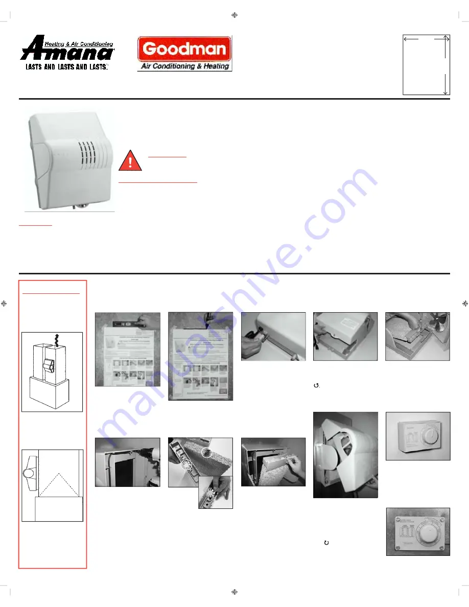
STEP-BY-STEP INSTALLATION INSTRUCTIONS
IMPORTANT:
+XPLGLÀHU
Placement
Information
Mount the Model
HUM-FP
Fan-Powered Flow-Thru
+XPLGLÀHURQWKH
WARM
AIR PLENUM ONLY.
3RVLWLRQWKHKXPLGLÀHUDV
shown in relation to the
AC cooling coils.
1.
Tape the template (this
entire sheet) onto the
warm air furnace plenum,
making sure it is level.
2.
Trace around the
template. (Cutout size is
13-1/8" wide by 16-1/2"
long.) Remove the template.
Accurately cut the plenum
opening.
3.
'LVFRQQHFWWKHKXPLGLÀHU
control wires by grasping
WKHQ\ORQFRQQHFWRUÀUPO\
and pulling straight out.
4.
Remove the cover by
turning the thumb screw
(circled) counter clockwise
Tilt and lift the cover
off the frame.
5.
Pull out the drip tray
and evaporator pad
assembly by grasping the
top lip and tipping out.
6.
Place the mounting
frame into the plenum
opening so that the frame
hooks over the bottom of
the opening. Screw the
frame to the plenum.
7.
Stand
the evapo-
rator pad
upright with
the black index mark on
top. Make sure the wick is
seated securely in the drip
tray.
8.
Place the drip tray on
top of the pad. Reinstall
the evaporator pad and
drip tray.
9.
Reattach the cover
assembly by hooking it at
the top of the mounting
frame. Secure the cover
by turning the thumb
screw at the bottom clock-
wise .
10.
Position the humidistat
on either
an interior wall
of
the home
or the return air
plenum
of the furnace. In-
stall by following the instruc-
tions in the parts bag.
See Additional Instructions on Back
Toll-free Contractor Helpline: 888-SKUTTLE (758-8853)
Contractor E-line: techservice@skuttle.com
IO-310
05/06
Goodman® is a registered trademark of Goodman Manufacturing Company, L. P.
Amana® is a trademark of Maytag Corporation and is used under license to Goodman Company, L. P.
All rights reserved.