background image

53

Maintenance

HIGH VOLTAGE !

T

O


AVOID


PERSONAL


INJURY


OR


DEATH


DUE


TO


ELECTRICAL


SHOCK

DISCONNECT


ELECTRICAL


POWER


BEFORE 

PERFORMING


ANY


SERVICE


OR


MAINTENANCE

.

WARNING

Annual Inspection

The furnace should be inspected by a qualified installer, or 

service agency at least once per year. This check should be 

performed at the beginning of the heating season. This will 

ensure that all furnace components are in proper working 

order and that the heating system functions appropriately. 

Pay  particular  attention  to  the  following  items.    Repair  or 

service as necessary.

• 

Flue  pipe  system.  Check  for  blockage  and/or 

leakage.  Check  the  outside  termination  and  the 

connections at and internal to the furnace.

• 

Heat exchanger. Check for corrosion and/or buildup 

within the heat exchanger passageways.

• 

Burners.  Check  for  proper  ignition,  burner  flame, 

and flame sense.

• 

Drainage  system.  Check  for  blockage  and/or 

leakage. Check hose connections at and internal 

to furnace.

• 

Wiring. Check electrical connections for tightness 

and/or corrosion. Check wires for damage.

• 

Filters.

T

O


AVOID


ELECTRICAL


SHOCK

INJURY


OR


DEATH

DISCONNECT


ELECTRICAL


POWER


BEFORE


PERFORMING


ANY


MAINTENANCE

. I

F


YOU


MUST


HANDLE


THE


IGNITER

HANDLE


WITH


CARE

. T

OUCHING


THE


IGNITER


ELEMENT


WITH


BARE


FINGERS

ROUGH


HANDLING


OR


VIBRATION


COULD


DAMAGE


THE


IGNITER


RESULTING


IN


PREMATURE


FAILURE

. O

NLY


A


QUALIFIED


SERVICER


SHOULD


EVER


HANDLE


THE


IGNITER

.

WARNING

Filters

Filter Maintenance

Improper filter maintenance is the most common cause of 

inadequate heating or cooling performance.  Filters should 

be cleaned (permanent) or replaced (disposable) every two 

months or as required. When replacing a filter, it must be 

replaced with a filter of the same type and size.

T

O


ENSURE


PROPER


UNIT


PERFORMANCE

ADHERE


TO


THE


FILTER


SIZES


GIVEN


IN


THE


RECOMMENDED

 M

INIMUM

 F

ILTER

 S

IZE

 T

ABLE


OR


S

PECIFICATION

 S

HEET


APPLICABLE


TO


YOUR


MODEL

.

CAUTION

Filter Removal

Depending on the installation, differing filter arrangements 

can be applied. Filters can be installed in either the central 

return  register  or  a  side  panel  external  filter  rack  (upflow 

only).  A media air filter or electronic air cleaner can be used 

as  an  alternate  filter.  Follow  the  filter  sizes  give  n  in  the 

Recommended Minimum Filter size table to ensure proper 

unit performance.
To remove filters from an external filter rack in an upright 

upflow installation, follow the directions provided with external 

filter rack kit.

Horizontal Unit Filter Removal

Filters in horizontal installations are located in the central 

return register or the ductwork near the furnace.
To remove:

1.  Turn OFF electrical power to furnace.

2.  Remove  filter(s)  from  the  central  return  register  or 

ductwork.

3.  Replace  filter(s)  by  reversing  the  procedure  for 

removal.

4.  Turn ON electrical power to furnace.

Media Air Filter or Electronic Air Cleaner 

Removal

Follow the manufacturer’s directions for service.

HIGH VOLTAGE !

T

O


AVOID


PERSONAL


INJURY


OR


DEATH


DUE


TO


ELECTRICAL


SHOCK

DISCONNECT


ELECTRICAL


POWER


BEFORE 

PERFORMING


ANY


SERVICE


OR


MAINTENANCE

.

WARNING

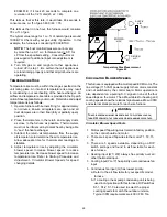
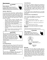
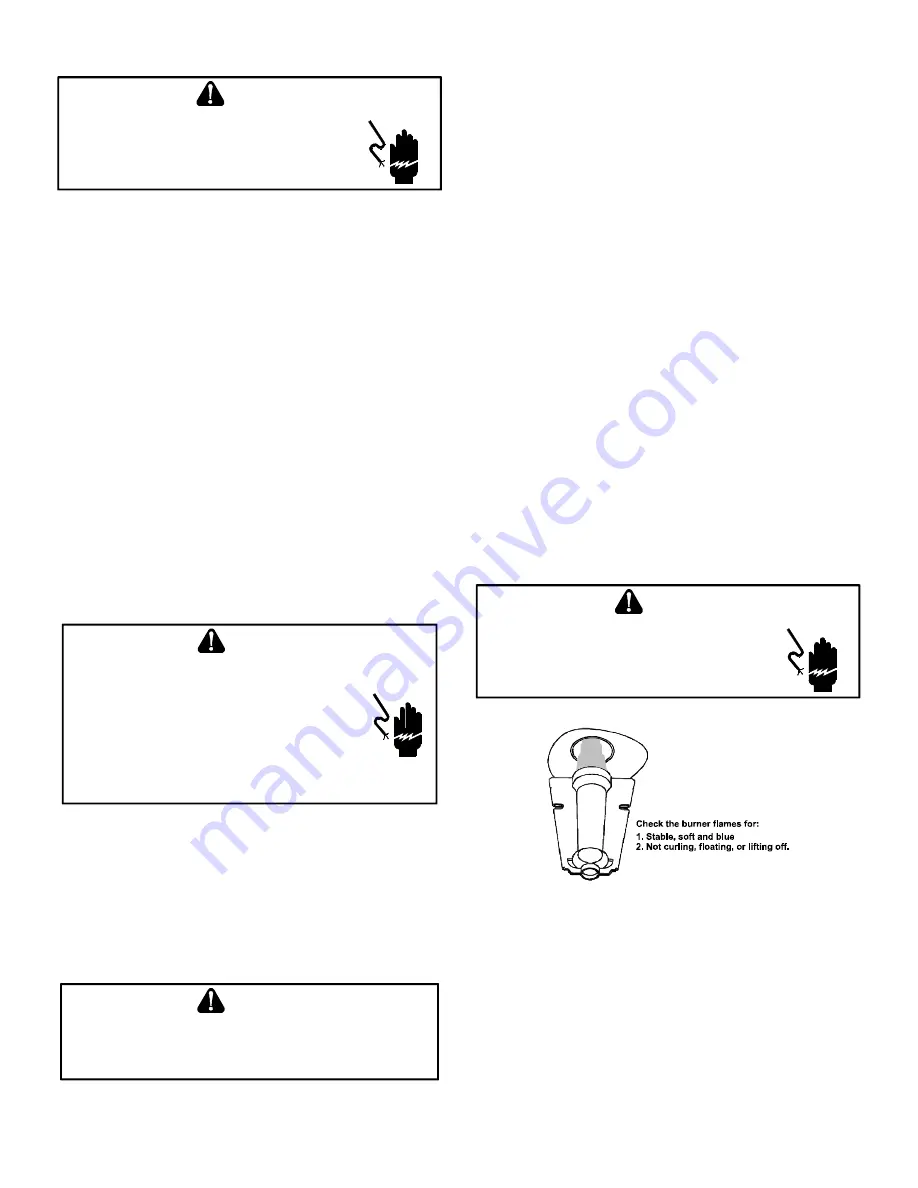
 Burner Flame

Figure 47

Burners

Visually  inspect  the  burner  flames  periodically  during  the 

heating season.  Turn on the furnace at the thermostat and 

allow several minutes for flames to stabilize, since any dis

-

lodged dust will alter the flames normal appearance. Flames 

should be stable, quiet, soft, and blue (dust may cause or

-

ange tips but they must not be yellow).  They should extend 

directly outward from the burners without curling, floating, or 

lifting off.  Flames must not impinge on the sides of the heat 

exchanger firing tubes.

Summary of Contents for *MEC96

Page 1: ...lease contact your distributor or our website for the applicable Specification Sheet referred to in this manual Thesefurnacescomplywithrequirements embodied in the American National Standard National Standard of Canada ANSI Z21 47 CSA 2 3 Gas Fired Central Furnaces ONLY PERSONNEL THAT HAVE BEEN TRAINED TO INSTALL ADJUST SERVICE OR REPAIR HEREINAFTER SERVICE THE EQUIPMENT SPECIFIED IN THIS MANUAL S...

Page 2: ...opane Gas High Altitude Installations 11 Condensate Drain Lines Drain Trap 18 Electrical Connections 23 Gas Supply and Piping 26 Circulating Air Filters 29 Startup Procedure Adjustment 32 Dip Switch Settings 34 Normal Sequence of Operation 49 Operational Checks 50 Safety Circuit Description 50 Troubleshooting 51 Maintenance 53 Before Leaving an Installation 54 Repair and Replacement Parts 54 Troub...

Page 3: ...his manual Always install a furnace to operate within the furnace s intended temperature rise range with a duct system which has external static pressure within the allowable range as specified on the furnace rating plate and OPERATIONAL CHECKS section of these instructions When a furnace is installed so that supply ducts carry air cir culated by the furnace to areas outside the space containing t...

Page 4: ...e and for a thorough investigation of each claim The distributor or manufacturer will not accept claims from dealers for transportation damage SHOULD OVERHEATING OCCUR OR THE GAS SUPPLY FAIL TO SHUT OFF TURN OFF THE MANUAL GAS SHUTOFF VALVE EXTERNAL TO THE FURNACE BEFORE TURNING OFF THE ELECTRICAL SUPPLY WARNING POSSIBLE PROPERTY DAMAGE PERSONAL INJURY OR DEATH DUE TO FIRE EXPLOSION SMOKE SOOT CON...

Page 5: ...s ó cuartos de servicio B10259 216 El monóxido de carbono puede causar enfermedades severas como daño cerebral permanente ó muerte Las emisiones de monóxido de carbono pueden circular a través del aparato cuando se opera en cualquier modo B10259 216 RISQUE D EMPOISONNEMENT AU MONOXYDE DE CARBONE Le monoxyde de des carbone peut causer des maladies graves telles que dommages permanents au cerveau et...

Page 6: ... capacity of the furnace should be greater than or equal to the total heat loss of the area to be heated The total heat loss should be calculated by an approved method or in accordance with ASHRAE Guide or Manual J Load Calculations published by the Air Conditioning Con tractors of America A copy of the CAN CSA B149 1 15 Installation Codes can also be obtained from CSA International 178 Rexdale Bo...

Page 7: ...nace must face the same direction If the furnace is installed in a residential garage position the furnace so that the burners and ignition source are located not less than 18 inches 457 mm above the floor Protect the furnace from physical damage by vehicles If the furnace is installed horizontally ensure the access doors are not on the up top or down bottom side of the furnace Do not connect this...

Page 8: ...ithin 12 inches of the bottom of the confined space In a typical construction the clearance between the door and door frame is usually ade quate to satisfy this ventilation requirement CARBON MONOXIDE POISONING HAZARD Failure to follow the steps outlined below for each appliance connected to the venting system being placed into operation could result in carbon monoxide poisoning or death The follo...

Page 9: ...res les ventilateurs les registres de foyer et tous les autres appareils de combustion alimentés au gaz doivent être remis dans leur état initial AVERTISSEMENT Existing Furnace Removal NOTE When an existing furnace is removed from a venting system serving other appliances the venting system may be too large to properly vent the remaining attached appliances The following vent testing procedure is ...

Page 10: ...doors and windows These changes have helped in reducing heating cooling costs but have created a problem supplying combustion and ventilation air for gas fired and other fuel burning appliances Appliances that pull air out of the house clothes dryers exhaust fans fireplaces etc increase the problem by starving appliances for air House depressurization can cause back drafting or improper combustion...

Page 11: ...ubing Drain Trap and Lines In horizontal applications the condensate drain trap is secured to the furnace side panel suspending it below the furnace A minimum clearance of 5 5 below the furnace must be provid ed for the drain trap Additionally the appropriate downward piping slope must be maintained from the drain trap to the drain location Refer to Condensate Drain Trap and Lines for further deta...

Page 12: ...mbustion to the outdoors as the vent pipe or flue pipe The pipe that supplies air for combustion to the furnace will be referred to as the intake pipe or combustion air pipe This furnace is dual certified and may be installed as a non direct vent single pipe or direct vent dual pipe appliance Materials Installations in the U S A PVC CPVC or ABS pipe fittings are typically used as venting and intak...

Page 13: ...TS ULC S636 WARNING Upon completion of the furnace installation carefully inspect the entire flue system both inside and outside of the furnace to assure it is properly sealed Leaks in the flue system can result in serious personal injury or death due to exposure to flue products including carbon monoxide WARNING Failure to follow these instructions can result in bodily injury or death Carefully r...

Page 14: ...ue Termination Forced Air Inlet Non Direct Vent Direct Vent Vent Flue Terminations Grade or Highest Anticipated Snow Level Vent Clearances Figure 7 VENT DRAIN RF000142 Coupling Figure 8 WARNING Edges of sheet metal holes may be sharp Use gloves as a precaution when removing hole plugs Figure 9 Insert flange Cut 2 long RF000142 SEE FIGURE 8 Figure 10 ...

Page 15: ...96 89 82 75 68 61 2 35 30 25 20 15 10 5 NA 3 103 96 89 82 75 68 61 54 2 45 40 35 30 25 20 15 10 3 110 103 96 89 82 75 68 61 MEC96 CEC96 Direct Vent 2 Pipe and Non Direct Vent 1 Pipe 6 Maximum Allowable Length of Vent Flue Pipe MODEL Pipe Size 4 in Number of Elbows 3 5 MEC960303AN MEC960403AN MEC960603AN MEC960302BN MEC960402BN MEC960603BN MEC960803BN MEC960804CN MEC961004CN MEC961005CN CEC960403BN...

Page 16: ...re 12 The RF000142 coupling Figure 8 can be secured directly to the furnace intake coupling if condensation is a concern If the RF000142 is used on the combustion air inlet it must be installed with the arrow pointing up It should be noted the combustion air will actually be moving in a direction opposite of the arrow on the RF000142 coupling It must have a field supplied trapped drain tube free d...

Page 17: ...ation Dual Pipe Figure 18 VENT FLUE TEE COMBUSTION AIR INTAKE DISTANCE BETWEEN COMBUSTION AIR INTAKE AND GRADE DISTANCE BETWEEN VENT AND GRADE Figure 19 Combustion Air Intake may also be snorkeled to obtain 12 min ground clearance 90 ELBOWS 3 24 BETWEEN PIPES Alternate vent termination above anticipated snow level dual pipe Figure 20 Vent Flue and Combustion Air Pipe Terminations 3 MIN 12 MIN TO G...

Page 18: ... products of combustion to the point where condensation takes place The condensate must be collected in the furnace drain trap and routed to an appropriate drain location in compliance with local and national codes Follow the bullets listed below when installing the drain system Refer to the following sections for specific details concerning furnace drain trap installation and drain hose hook ups ...

Page 19: ...THE LATEST EDITION OF THE NATIONAL ELECTRIC CODE WARNING WARNING TO AVOID THE RISK OF INJURY ELECTRICAL SHOCK OR DEATH THE FURNACE MUST BE ELECTRICALLY GROUNDED IN ACCORDANCE WITH LOCAL CODES OR IN THEIR ABSENCE WITH THE LATEST EDITION OF THE NATIONAL ELECTRICAL CODE Upflow Model Installed Vertically The trap and factory installed hoses remain as shipped The furnace drain may exit either the right...

Page 20: ... section Insert hose 2 from outside the cabinet through the cabinet drain hole nearest the top Secure it to the barbed fitting in the elbow with a red clamp 6 For models DM96VE0303AN DM96VE0403AN and DM96VE0603AN locate the hose 2 factory installed and cut 1 5 length from the end of the hose Insert hose 2 from outside the cabinet through the cabinet drain s hole nearest to the top Secure it to the...

Page 21: ...d Horizontally with Left Side Down Alternate See Figure 29 Also see Front Cover Pressure Switch Tube Location on page 11 1 Draining the RF000142 Coupling Locate hose 2 factory installed Cut off and discard the 45 radius end 2 Install 90 radius end of hose 2 on RF000142 drain outlet and secure with a red clamp 3 Insert coupling in hose 2 and secure with a red clamp 4 Locate hose 5 and cut 3 from th...

Page 22: ...f furnace trap Figure 31 Counterflow Model Installed Horizontal ly with Right Side Down See Figure 32 Minimum 5 1 2 clearance is required for the drain trap be neath the furnace NOTE For horizontal installations some of the required hoses are found in the factory installed hose assemblies Remove the hose clamps to obtain the respective hoses needed for installation and install per the following di...

Page 23: ...unt tool such as a 3 16 Allen wrench into the center of the rubber plug will stretch the plug and allow complete insertion 9 Place radius end of hose 4 on the side port of vent drain elbow and secure with a gold clamp 10 Insert a diameter PVC pipe factory installed into hose 4 and secure with a gold clamp 11 Insert the non grommet end of hose 5 factory installed from outside the cabinet in the bac...

Page 24: ...Junction Box Relocation EDGES OF SHEET METAL HOLES MAY BE SHARP USE GLOVES AS A PRECAUTION WHEN REMOVING HOLE PLUGS WARNING TO PREVENT PERSONAL INJURY OR DEATH DUE TO ELECTRIC SHOCK DISCONNECT ELECTRICAL POWER BEFORE INSTALLING OR SERVICING THIS UNIT WARNING HIGH VOLTAGE TO AVOID THE RISK OF INJURY ELECTRICAL SHOCK OR DEATH THE FURNACE MUST BE ELECTRICALLY GROUNDED IN ACCORDANCE WITH LOCAL CODES O...

Page 25: ...ry Setting DIP SWITCH SWITCH GROUP FUNCTION S3 S3 Heating Fan Off Delay PURPOSE Thermostat Setup Fossil Fuel Applications This furnace can be used in conjunction with a heat pump in a fossil fuel application A fossil fuel application refers to a combined gas furnace and heat pump installation which uses an outdoor temperature sensor to determine the most cost efficient means of heating heat pump o...

Page 26: ...r cleaner terminal EAC is energized with 115 volts whenever the circulator blower is energized This terminal can also be used to provide 115 volt power to a humidifier transformer The remaining primary transformer wire would be connected to the Line N on the control board HIGH VOLTAGE TO AVOID PERSONAL INJURY OR DEATH DUE TO ELECTRICAL SHOCK DISCONNECT ELECTRICAL POWER BEFORE SERVICING OR CHANGING...

Page 27: ...it Taps for measuring the gas supply pressure and manifold pressure are provided on the valve The gas valve has a manual ON OFF control located on the valve itself This control may be set only to the ON or OFF position Refer to the lighting instructions label or Startup Procedure Adjustment for use of this control during start up and shut down periods Gas Piping Connections The gas piping supplyin...

Page 28: ...shaped manifold a 2 long nipple is required Asemi rigid connector to the gas piping can be used outside the cabinet per local codes From the elbow the length of pipe and the fittings required will vary by the side chosen location of union and cabinet width The union may be placed inside or outside of the cabinet Alternate Gas Line Location Gas Valve Burners Manual Shut Off Valve upstream from grou...

Page 29: ...rwriters for the Installation of Air Conditioning Warm Air Heating and Ventilating Systems Pamphlets No 90A and 90B Aclosed return duct system must be used with the return duct connected to the furnace NOTE Ductwork must never be attached to the back of the furnace For upflow installations requiring 1800 CFM or more use either two side returns or bottom return or a combination of side bottom Flexi...

Page 30: ...he furnace rating plate Checking Static Pressure 80 Furnace Shown 90 Similar Figure 41 Air Cleaner Installation Location Maximum Heating Airflow Filter Media Dimensions Part Number Air Cleaner Family Side or bottom return 1200 CFM 16 in X 20 in x 5 AM11 1620 5 Side or bottom return 1600 CFM 16 in X 25 in x 5 AM11 1625 5 Side or bottom return 1600 CFM 20 in X 20 in x 5 AM11 2020 5 Side or bottom re...

Page 31: ...the building owner Filters do not ship with this furnace but must be provided sized and installed externally by the installer Filters must comply with UL900 or CAN ULCS111 standards Damage or repairs due to the installation of the furnace without filters is not covered under the warranty On upflow units guide dimples locate the side return cutout locations Useastraightedgetoscribelinesconnectingth...

Page 32: ...furnace 3 Set the room thermostat to the lowest possible setting 4 Remove the burner compartment door NOTE This furnace is equipped with an ignition device which automatically lights the burner Do not try to light the burner by hand 5 Move the furnace gas valve manual control to the OFF position 6 Wait five minutes then smell for gas Be sure check near the floor as some types of gas are heavier th...

Page 33: ...sure table shown below Range Nominal Natural Low Stage 1 6 2 2 w c 1 9 w c High Stage 3 2 3 8 w c 3 5 w c Propane Low Stage 5 7 6 3 w c 6 0 w c High Stage 9 7 10 3 w c 10 0 w c Manifold Gas Pressure Gas 8 Remove regulator cover screw from the low LO outlet pressure regulator adjust tower and turn screw clockwise to increase pressure or counterclockwise to decrease pressure Replace regulator cover ...

Page 34: ...2 3 4 Heating CFM Switches Continuous Fan CFM Switches Thermostat Selection Switches 1 2 3 4 2 Stage Stat OFF OFF 1 Stg Stat 10 min delay ON OFF 1 Stg Stat 20 min delay ON ON Auto OFF ON 90 OFF OFF 120 OFF ON 150 ON OFF 180 ON ON FACTORY SETTING Dip Switch Switch Group Function S3 S3 Heating Fan Off Delay Purpose Thermostat Setup ...

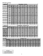
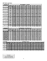
Page 35: ... CFM CFM CFM CFM CFM CFM OFF OFF OFF G 743 688 628 572 515 459 408 364 ON OFF OFF G 939 894 846 806 759 706 661 614 ON ON OFF G 1137 1096 1056 1018 981 940 897 859 OFF ON OFF G 647 576 511 449 387 335 280 252 OFF OFF ON G 1229 1181 1150 1117 1078 1035 1002 964 OFF ON ON G 743 688 628 572 515 459 408 364 ON OFF ON G 743 688 628 572 515 459 408 364 ON ON ON G 743 688 628 572 515 459 408 364 DIP Swit...

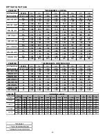
Page 36: ...CFM CFM CFM CFM CFM CFM OFF OFF OFF G 899 845 788 729 671 607 558 504 ON OFF OFF G 1342 1304 1254 1219 1174 1127 1090 1045 ON ON OFF G 752 609 534 460 396 345 N A N A OFF ON OFF G 1167 1122 1074 1029 984 935 885 840 OFF OFF ON G 1252 1206 1164 1118 1077 1034 991 945 OFF ON ON G 899 845 788 729 671 607 558 504 ON OFF ON G 899 845 788 729 671 607 558 504 ON ON ON G 899 845 788 729 671 607 558 504 DI...

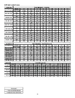
Page 37: ...FM CFM OFF OFF OFF G 1221 1176 1136 1094 1050 1013 971 928 ON OFF OFF G 1323 1287 1253 1207 1168 1129 1087 1052 ON ON OFF G 705 631 567 498 439 385 317 N A OFF ON OFF G 920 868 813 760 713 653 602 561 OFF OFF ON G 1130 1085 1040 993 948 900 853 814 OFF ON ON G 1221 1176 1136 1094 1050 1013 971 928 ON OFF ON G 1221 1176 1136 1094 1050 1013 971 928 ON ON ON G 1221 1176 1136 1094 1050 1013 971 928 DI...

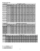
Page 38: ...L CFM CFM CFM CFM CFM CFM CFM CFM OFF OFF OFF G 1300 1234 1175 1109 1052 992 928 866 ON OFF OFF G 1866 1817 1774 1729 1684 1637 1593 1552 ON ON OFF G 1477 1422 1364 1301 1244 1190 1135 1078 OFF ON OFF G 1637 1577 1528 1467 1410 1369 1307 1256 OFF OFF ON G 2069 2009 1978 1932 1923 1876 1834 1773 OFF ON ON G 1300 1234 1175 1109 1052 992 928 866 ON OFF ON G 1300 1234 1175 1109 1052 992 928 866 ON ON ...

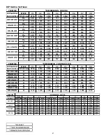
Page 39: ...M CFM CFM CFM CFM CFM CFM CFM OFF OFF OFF G 623 506 451 393 343 293 N A N A ON OFF OFF G 755 710 672 627 582 534 491 447 ON ON OFF G 653 597 552 507 460 410 366 326 OFF ON OFF G 914 874 841 805 772 732 696 657 OFF OFF ON G 1070 1040 1005 975 942 915 883 849 OFF ON ON G 623 506 451 393 343 293 N A N A ON OFF ON G 623 506 451 393 343 293 N A N A ON ON ON G 623 506 451 393 343 293 N A N A DIP Switche...

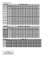
Page 40: ...CFM CFM CFM CFM CFM CFM CFM CFM OFF OFF OFF G 721 679 635 591 552 505 463 422 ON OFF OFF G 1070 1040 1005 975 942 915 883 849 ON ON OFF G 653 597 552 507 460 410 366 326 OFF ON OFF G 914 874 841 805 772 732 696 657 OFF OFF ON G 1191 1168 1135 1112 1081 1055 1024 998 OFF ON ON G 721 679 635 591 552 505 463 422 ON OFF ON G 721 679 635 591 552 505 463 422 ON ON ON G 721 679 635 591 552 505 463 422 ME...

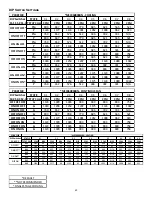
Page 41: ...FM OFF OFF OFF G 1254 1230 1199 1171 1139 1115 1086 1053 ON OFF OFF G 1330 1301 1274 1244 1227 1191 1163 1132 ON ON OFF G 697 654 600 557 508 460 419 371 OFF ON OFF G 880 838 794 763 722 689 644 606 OFF OFF ON G 1056 1026 991 961 929 894 864 829 OFF ON ON G 1254 1230 1199 1171 1139 1115 1086 1053 ON OFF ON G 1254 1230 1199 1171 1139 1115 1086 1053 ON ON ON G 1254 1230 1199 1171 1139 1115 1086 1053...

Page 42: ... CFM CFM CFM CFM CFM OFF OFF OFF G 936 888 832 778 723 657 603 549 ON OFF OFF G 1149 1101 1052 1006 967 916 866 821 ON ON OFF G 781 628 547 470 396 333 N A N A OFF ON OFF G 1332 1291 1252 1218 1173 1134 1088 1049 OFF OFF ON G 1240 1194 1153 1104 1069 1019 971 929 OFF ON ON G 936 888 832 778 723 657 603 549 ON OFF ON G 936 888 832 778 723 657 603 549 ON ON ON G 936 888 832 778 723 657 603 549 DIP S...

Page 43: ... CFM CFM CFM CFM OFF OFF OFF G 1123 1078 1035 993 949 894 809 758 ON OFF OFF G 1318 1299 1254 1207 1175 1124 1089 1042 ON ON OFF G 760 652 576 512 446 392 331 N A OFF ON OFF G 899 847 788 770 685 621 565 521 OFF OFF ON G 1226 1177 1133 1091 1052 1008 962 923 OFF ON ON G 1123 1078 1035 993 949 894 809 758 ON OFF ON G 1123 1078 1035 993 949 894 809 758 ON ON ON G 1123 1078 1035 993 949 894 809 758 D...

Page 44: ... CFM CFM CFM CFM CFM OFF OFF OFF G 1281 1220 1152 1096 1031 978 914 856 ON OFF OFF G 1839 1790 1757 1699 1665 1615 1568 1527 ON ON OFF G 1408 1337 1279 1218 1167 1112 1062 999 OFF ON OFF G 1185 1121 1058 992 933 868 808 750 OFF OFF ON G 1727 1691 1642 1600 1545 1504 1449 1410 OFF ON ON G 1281 1220 1152 1096 1031 978 914 856 ON OFF ON G 1281 1220 1152 1096 1031 978 914 856 ON ON ON G 1281 1220 1152...

Page 45: ...M CFM CFM CFM OFF OFF OFF G 1522 1464 1402 1338 1280 1230 1167 1101 ON OFF OFF G 1861 1803 1749 1698 1653 1594 1549 1504 ON ON OFF G 1004 890 805 710 620 553 474 406 OFF ON OFF G 1312 1235 1170 1101 1037 962 880 820 OFF OFF ON G 1772 1713 1662 1609 1540 1498 1452 1399 OFF ON ON G 1522 1464 1402 1338 1280 1230 1167 1101 ON OFF ON G 1522 1464 1402 1338 1280 1230 1167 1101 ON ON ON G 1522 1464 1402 1...

Page 46: ...FM CFM CFM CFM CFM CFM OFF OFF OFF G 1283 1219 1162 1109 1036 974 917 864 ON OFF OFF G 1811 1772 1733 1690 1644 1590 1551 1492 ON ON OFF G 1438 1366 1309 1254 1163 1133 1077 1013 OFF ON OFF G 1384 1324 1271 1204 1145 1088 1029 985 OFF OFF ON G 2008 1963 1944 1916 1876 1839 1801 1759 OFF ON ON G 1283 1219 1162 1109 1036 974 917 864 ON OFF ON G 1283 1219 1162 1109 1036 974 917 864 ON ON ON G 1283 12...

Page 47: ... CFM CFM CFM OFF OFF OFF G 1796 1753 1697 1645 1589 1536 1478 1425 ON OFF OFF G 2211 2163 2122 2076 2029 1986 1964 1942 ON ON OFF G 1106 1017 946 855 764 681 605 550 OFF ON OFF G 1399 1327 1259 1185 1119 1051 980 913 OFF OFF ON G 1683 1628 1565 1511 1445 1387 1340 1276 OFF ON ON G 1796 1753 1697 1645 1589 1536 1478 1425 ON OFF ON G 1796 1753 1697 1645 1589 1536 1478 1425 ON ON ON G 1796 1753 1697 ...

Page 48: ...temperature to determine the air temperature rise Allow adequate time for thermometer readings to stabilize 4 Adjust temperature rise by adjusting the circulator blower speed Increase blower speed to reduce temperature rise Decrease blower speed to increase temperature rise Refer to Startup Procedure and Adjustment Circulator Blower Speeds for speed changing details SUPPLY AIR RETURN AIR Temperatu...

Page 49: ...nce the low pressure switch is detected open the inducer blower is energized at high speed and the humidifier is enabled The low pressure switch is checked for closure Once the low pressure switch is closed the pre purge period begins The inducer will be energized at high speed for the pre purge period Following the completion of pre purge the inducer switches to low speed and the igniter warm up ...

Page 50: ...help avoid exposing the integrated control module to electrostatic discharge This procedure is applicable to both installed and uninstalled ungrounded furnaces After the thermostat is satisfied the compressor is de energized and the 45 second fan off delay period begins Following the 45 second cool mode fan off delay period the cool circulator and air cleaner relay are de energized Single cooling ...

Page 51: ...does not close within five minutes the control assumes the blower has failed the RED LED will flash ELEVEN times If the limit circuit opens and does not close within fifteen minutes the control assumes the manual rollout or fuse has opened and the RED LED will flash FIVE times The control will enter a one hour lockout and the inducer will run continuously In an open limit condition the red LED wil...

Page 52: ...ich originally caused the lockout still exists the control will return to lockout Refer to the Troubleshooting Chart for aid in determining the cause Fault Code Reset To clear the fault code memory push and hold the LAST ERROR button for more than 5 seconds and less than 10 seconds the LED will indicate this period by RAPID GREEN FLASH for 5 seconds to 10 seconds The LED will flash three green fla...

Page 53: ...ter of the same type and size TO ENSURE PROPER UNIT PERFORMANCE ADHERE TO THE FILTER SIZES GIVEN IN THE RECOMMENDED MINIMUM FILTER SIZE TABLE OR SPECIFICATION SHEET APPLICABLE TO YOUR MODEL CAUTION Filter Removal Depending on the installation differing filter arrangements can be applied Filters can be installed in either the central return register or a side panel external filter rack upflow only ...

Page 54: ...sense signal If the flame sense signal drops too low the furnace will not sense flame and will lock out The flame sensor should be carefully cleaned by a qualified servicer using steel wool Flue Passages Qualified Servicer Only The heat exchanger flue passageways should be inspected at the beginning of each heating season Before Leaving an Installation Cycle the furnace with the thermostat at leas...

Page 55: ...fore proceeding with work Furnace does not operate three Amber flashes on control board None Three repeating flashes None W2 call present without W1 Faulty thermostat or thermostat wiring or improperly connected thermostat wires Confirm electrically safe condition before proceeding with repairs Furnace does not operate four Amber flashes on control board None Four repeating flashes None Ylo or Y c...

Page 56: ...irs Furnace does not operate nine Red flashes on control board None None Nine repeating flashes Improper grounding or reverse polarity 115 volt hot neutral supply to furnace reversed hot wire door switch L1 on control board must read 115 volts to ground neutral Neutral wire should measure 0 volts to ground Confirm electrically safe condition before proceeding with repairs Furnace does not operate ...

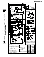
Page 57: ...GND INTERNAL TO SWITCH PRESSURE HIGH FIRE PROT DEVICE INTEGRATED CONTROL PK PU PLUG CONNECTION L N BK C DOOR OPEN OPEN WHEN DOOR SWITCH COMPARTMENT BLOWER SWITCH TEMP GND 1 BLOWER CIRCULATOR JUNCTION OR 40 VA Ø 60 HZ DISCONNECT WHITE RODGERS GAS VALVE TWO STAGE OVERCURRENT CONNECTOR 2 CIRCUIT LOW VOLTAGE 24V YL GND WH CHASSIS GROUND 2 3 IGNITER SURFACE HOT 2 YL PU C 2 C BLOWER DRAFT INDUCED BK PM ...

Page 58: ...size no less than one half 1 2 inch in size GAS VENT DIRECTLY BELOW KEEP CLEAR OF ALL OBSTRUCTIONS 4 INSPECTION The state or local gas inspector of the side wall horizontally vented gas fueled equipment shall not approve the installation unless upon inspection the inspector observes carbon monoxide detectors and signage installed in accordance with the provisions of 248 CMR 5 08 2 a 1 through 4 EX...

Page 59: ...59 THIS PAGE IS INTENTIONALLY LEFT BLANK ...

Page 60: ...u purchased to be directed to the feedback page GOODMAN BRAND AMANA BRAND GOODMAN BRAND AMANA BRAND PRODUCT REGISTRATION Thank you for your recent purchase Though not required to get the protection of the standard warranty registering your product is a relatively short process and entitles you to additional warranty protection except that failure by California and Quebec residents to register thei...

Reviews: