background image

IMPORTANT SAFEGUARDS

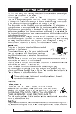
For your own safety read following instructions carefully before attempting to
connect this clock radio to the mains.
Mains Supply:

230V ~ 50Hz - AC only

This unit is designed to operate on a 230V ~ 50Hz supply only.  Connecting it
to other power sources may damage it.  Ensure that the supply corresponds
to the information on the rating label on the bottom of the unit.
This clock radio may be fitted with a non-rewireable plug.  If it is neccssary to
change the fuse in a non-rewireable plug the fuse cover must be refitted.
If the fuse cover becomes lost or damaged, the plug must not be used until a
replacement, available from the manufacturer, is obtained.  It is important that
the colour of the replacement fuse cover corresponds with the colour marking
on the base of the plug.
If the plug needs to be changed because it is not suitable for your socket, or
becomes damaged, it should be cut off and an appropriate plug fitted following
the wiring instructions below.  The plug must then be disposed of safely, as
insertion into a 13A socket is likely to cause an electrical hazard.

IMPORTANT

The wires in the mains plug should be connected
as shown in the diagram.
The colours of the wires in the mains lead of the unit
may not correspond with the coloured markings
identifying the terminals in your plug.  Connect them
as follows:-
The wire which is coloured blue must be cpmmected to the terminal which is
marked with the letter ‘N’ or coloured black.
The wire which is coloured brown must be connected to the terminal which is
marked with the letter ‘L’ or coloured red.
There should be no connection to the earth terminal of your plug.
If a 13 Amp (BS 1363) Plug is used, a 3 Amp Fuse must be fitted, or if any
other type of Plug is used a 3 Amp or 5 Amp Fuse must be fitted, either in the
Plug or Adaptor, or on the Distribution Board.

This symbol means that this unit is double insulated.  An earth 
connection is not required.

DANGER

LASER SAFETY

CAUTION:  USE OF CONTROLS OR ADJUSTMENTS OR
PERFORMANCE OF PROCEDURES OTHER THAN SPECIFIED
HEREIN MAY RESULT IN HAZARDOUS RADIATION EXPOSURE.
INVISIBLE LASER RADIATION WHEN OPEN AND INTERLOCK
FAILED OR DEFEATED.  AVOID DIRECT EXPOSURE TO
This unit employs a laser.  Only a qualified service person should remove the
cover or attempt to service.

CAUTION

To prevent electric shock, disconnect from the mains before removing cover.
No user serviceable parts inside.  Refer servicing to qualified service personnel.

BLUE

(NEUTRAL)

N

BROWN

(LIVE)

L

FUSE

OUTER

SLEEVE

CORD GRIP

Goodmans Product Information Helpline (02392) 391100

Summary of Contents for GCE5001DVD

Page 1: ...INSTRUCTION MANUAL Model GCE 5001DVD Home and Go DVD CD Player with Monitor 083286 Goodmans Product Information Helpline 02392 391100...

Page 2: ...colours of the wires in the mains lead of the unit may not correspond with the coloured markings identifying the terminals in your plug Connect them as follows The wire which is coloured blue must be...

Page 3: ...t the volume is too loud Remember listening for prolonged period of time at high volume levels will harm your hearing Once you have established a comfortable listening level DO NOT INCREASE THE SOUND...

Page 4: ...r Washing Do not expose the product to water or excessive moisture This could cause electrical shorts fire or other damage When Parked Parking in direct sunlight can produce very high temperatures ins...

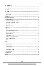
Page 5: ...eys 11 Preparing the Remote Control 13 Loading a disc 13 Ejecting a disc 13 Operation 14 Basic Play 14 On Screen Display Function 16 Multi audio Language Function 17 Menu Function 17 Title Menu Functi...

Page 6: ...USE ONLY THE RECOMMENDED ACCESSORIES THIS DEVICE IS INTENDED FOR CONTINUOUS OPERATION This product incorporates copyright protection technology that is protected by method claims of certain U S paten...

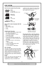
Page 7: ...alcohol Never use solvents such as benzine thinner or conventional record cleaners as they may mar the surface of the disc Note A disc may become scratched although not enough to make it unusable depe...

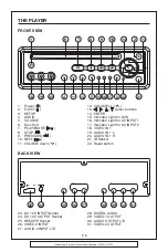
Page 8: ...ER 15 Indicator Light for DVD 16 Indicator Light for AV INPUT 1 17 Indicator Light for AV INPUT 2 18 VIDEO IN 1 19 AUDIO IN 1 L 20 AUDIO IN 1 R 21 IR Sensor 22 Reset button 23 DC 12V INPUT Socket 24 D...

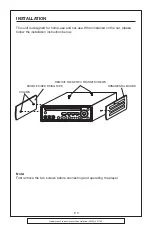
Page 9: ...unit is designed for home use and car use When installed on the car please follow the installation instruction below Note First remove the two screws before connecting and operating the player COLUMN...

Page 10: ...2 OUT DVD PLAYER AC DC ADAPTOR CIGARETTE LIGHTER VIDEO 2 IN AUDIO 2 R IN AUDIO 2 L IN WHITE RED YELLOW DC 12V IN REMOTE INPUT OUTPUT VIDEO L R A V 2 INPUT DIGITAL AUDIO A V OUTPUT VIDEO 1 VIDEO 2 L R...

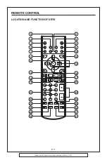
Page 11: ...Goodmans Product Information Helpline 02392 391100 REMOTE CONTROL LOCATION AND FUNCTION OF KEYS 6 1 3 7 11 4 8 10 5 9 12 13 14 16 15 17 20 18 19 24 21 28 22 32 23 25 29 27 26 31 30 2 P 11...

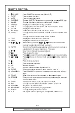
Page 12: ...irm the Track Chapter selected with the numeric buttons or selected with the cursor buttons on TV screen 15 Slow motion forward reverse playback 16 Press to play the disc 17 Press to search forward ra...

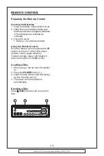
Page 13: ...r Battery Two AAA size battery Using the Remote Control Point the remote control towards the IR sensor on the front of the DVD player remote control signal receiver Operation angle About 30 degree in...

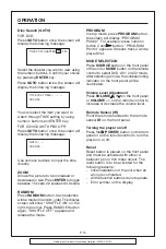
Page 14: ...s according to the disc as follow DVD Normal Playback 2X 4X 8X Pause still picture Pressing on the remote control or on the front panel during playback will stop play temporary To return to normal pla...

Page 15: ...again SHUFFLE OFF appears and release the mode PROGRAM In stop mode press PROGRAM button the screen will display PROGRAM P00 00 For example press numeric button 4 and button PROGRAM P01 04 appears It...

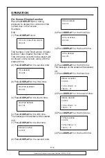
Page 16: ...ress DISPLAY for the fourth time CHAPTER REMAIN 00 01 39 5 Press DISPLAY for the fifth time The message on the screen will be cleared VCD 1 Press DISPLAY for the first time SINGLE ELAPSED 00 00 25 2 P...

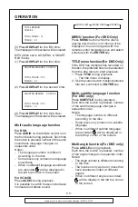
Page 17: ...or DVD Only Press MENU button while the disc is playing and the disc root menu will be displayed You can navigate with the remote control navigation keys and select a feature with the ENTER key TITLE...

Page 18: ...in FOLDER REP Play all songs in the current directory in sequence over and again FOLDER Play all songs in the current directory once Use the to select play mode When play mode is selected use to chang...

Page 19: ...ems for AUDIO Please refer to AUDIO SETUP MENU d PREFERENCES SETUP This setup menu includes all the configuration of support feature Please refer to PREFERENCES SETUP MENU GENERAL SETUP GENERAL PAGE T...

Page 20: ...ase note If the DVD disc is not recorded with multiple angles the angle mark will not appear at all GENERAL PAGE OSD LANG type setup Select the preferred OSD language by using the buttons GENERAL PAGE...

Page 21: ...mode to active analog audio output Select SPDIF RAW mode to activate raw digital audio output And the digital audio format depends on the disc record format Select SPDIF PCM mode to active PCM digital...

Page 22: ...rmat Select NTSC format when you connected to NTSC TV Select PAL format when you connected to PAL TV Select AUTO format the player output format will be according to the DVD disc format PREFERENCES PA...

Page 23: ...press ENTER button Type the old password The initial code is 3308 and key in a new 4 characters password you want to use and retype again to confirm key in correctly TV TYPE AUDIO SUBTITLE DISC MENU P...

Page 24: ...RD DEFAULTS SMART NAV MAIN PAGE NO MENU WITH MENU TV TYPE AUDIO SUBTITLE DISC MENU PARENTAL PASSWORD DEFAULTS SMART NAV MAIN PAGE General Setup TV Display Normal LB PIC Mode AUTO Angle Mark ON OSD Lan...

Page 25: ...2 S N ratio 80 dB JIS 3 Wow and Flutter Below measurable limits Note Specifications and design are subject to modification without notice due to improvements in technology This product incorporates c...

Page 26: ...Goodmans Product Information Helpline 02392 391100 P 26 OWNER S MANUAL MONITOR 022929...

Page 27: ...pin mini din socket 2 2 The yellow socket 3 is connected to the VIDEO socket The white socket 4 is connected to the AUDIO Out Left socket and the red socket 5 is connected to the AUDIO Out Right sock...

Page 28: ...P 28 Goodmans Product Information Helpline 02392 391100 CONTROL FUNCTION KEYS 5 inch COLOUR TFT LCD MONITOR 9 1 2 5 6 7 8 4 13 12 10 11 11 10 3...

Page 29: ...to adjust the contrast level 7 BRIGHTNESS Rotate the BRIGHT knob 8 right or left to adjust the brightness level 8 TFT LIQUID CRYSTAL DISPLAY The display will show the DVD movie 9 SOCKET FOR HEADPHONES...

Reviews: