background image

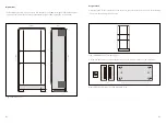
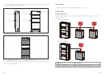
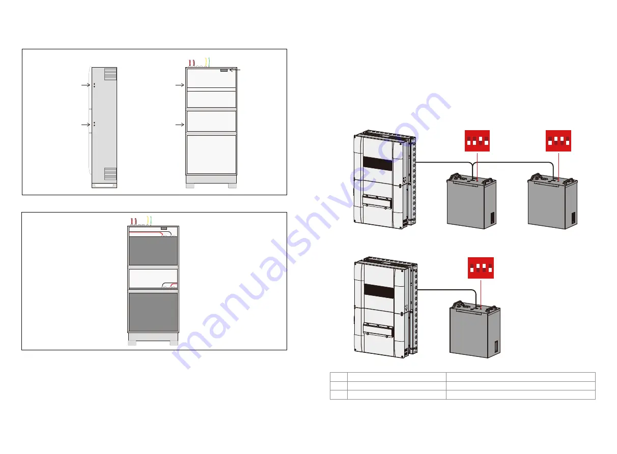
Figure 9: BCL0096 earthing connection points.

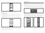
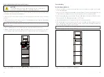
Figure 10: BCL0096 with batteries and connected (GoodWe SECU-A).
At this stage the preliminary installation of the Battery Enclosure is complete. The next step is the 
connection of the BMS cables.

3.If you are using GoodWe SECU-A battery packs, connect the bonding leads between each battery 

and the earthing studs inside the enclosure.

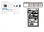
BMS connection 

The BMS communication for GoodWe SECU-A battery is as follows:

GoodWe SECU-A

2x earthing points

2x earthing points

2x earthing points

Side of Battery Enclosure

(wire-frame view)

2x earthing points

Fan Controller

Front view of Battery Enclosure

DIP Switch Calibration

The DIP switches shall be configured differently between single piece battery and 2 battery 
paralleling system.
2* Pack System (10.8kWh)

1* Pack System (5.4kWh)

Function

Terminal Resistance Switch
GoodWe communication protocol Switch

DIP

2
3

Description

To recognize the last battery connected to inverter
To relize the communication between inverter and inverter unit part

07

08

1 2 3 4

ON

DIP

1 2 3 4

ON

DIP

1 2 3 4

ON

DIP

Summary of Contents for BCL0096

Page 1: ...Installation Manual Smart Hybrid Battery Enclosure BCL0096 V1 0 340 00429 00...

Page 2: ...968 No part may be reproduced by any process nor may any other exclusive right be exercised without the permission of GoodWe Technologies Limited Privacy notice GoodWe will use the information provide...

Page 3: ...he location selected for the Battery Enclosure installation There should be ample room min 150mm for air circulation around the Battery Enclosure as the Battery Enclosure uses fans to circulate air th...

Page 4: ...width 535mm depth 280mm height 1205mm with the feet installed Figure 1 Dimensions Figure 2 BCL0096 out of the packing box Figure 3 Battery Enclosure feet and mounting screws 1 In preparation for the i...

Page 5: ...he respective power leads into the power connectors on the batteries while taking note of the polarity Ensure that the battery 2 lead which has the power connector for the Fan Controller is plugged in...

Page 6: ...y is as follows GoodWe SECU A 2x earthing points 2x earthing points 2x earthing points Side of Battery Enclosure wire frame view 2x earthing points Fan Controller Front view of Battery Enclosure DIP S...

Page 7: ...of the master battery Master battery COM 1 port to Inverter port Link port COM 1 of the slave battery From To Cable label APP Setting On PV Master To make sure the battery communicates to inverter un...

Page 8: ...BoS box and the Battery Enclosure s front cover still open turn on the Invert er and subsequently close the battery breaker in preparation for the commissioning process CAUTION GoodWe Battery SECU A 1...

Page 9: ...Notes 13...

Reviews: