12
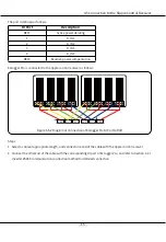
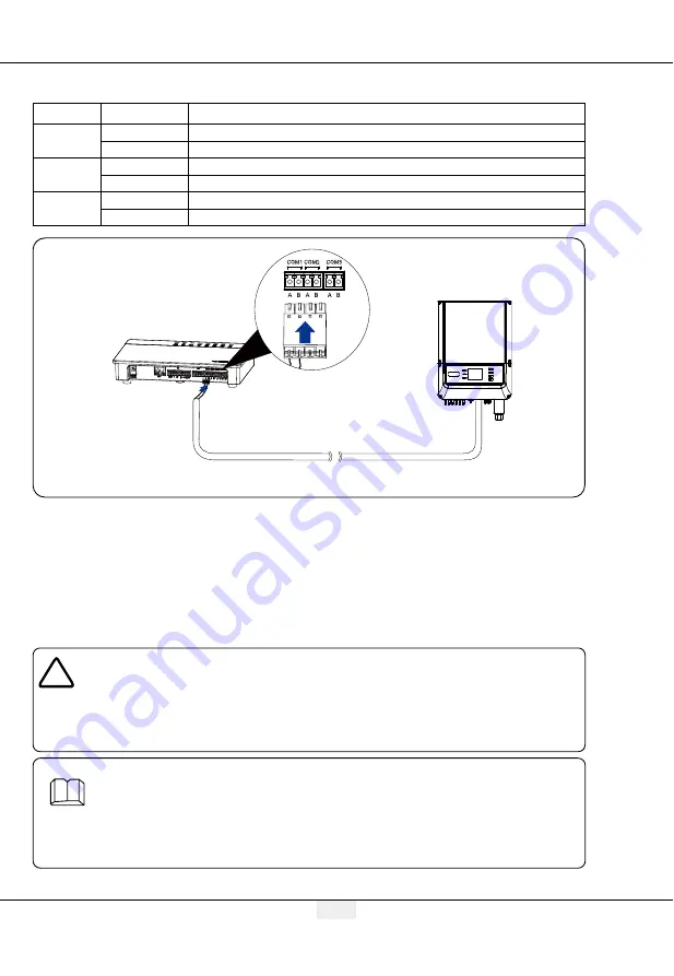
Figure 4.2.1-2 Wiring Diagram of EzLogger Pro COM Ports
COM ports are described as follows:
Port
Symbol
Description
COM1
A
RS485A, RS485 differential
B
RS485B, RS485 differential signal -
COM2
A
RS485A, RS485 differential
B
RS485B, RS485 differential signal -
COM3
A
RS485A, RS485 differential
B
RS485B, RS485 differential signal -
Steps:
1. Select a RS485 communication cable of appropriate length (
≤
1000m).
2. First strip off the insulating layer at both ends of the communication cable.
3. Then connect one core of the communication cable with terminal A of EzLogger Pro COM port, and the
other core with terminal B of EzLogger Pro COM port.
4. Another side connect to inverter,please refer to the meaning of RS485 port of inverter.
Note that COM"A" of Ezlogger Pro connect to the RS485"A" of inverter, COM"B" of Ezlogger Pro connect
to the RS485"B" of inverter.
1. RS485 communication cable shall be a standard RS485 communication shielded twisted
pair wire.
2. Inverter communication cable can only be connected to EzLogger Pro's COM1, COM2 and
COM3.
3. A single COM port of EzLogger Pro supports a maximum of 20 inverters, and 3 COM ports
support a total of 60 inverters.
Description of connection of communication cable with the terminal block:
1. First press and hold the corresponding white contact sheet of the wiring terminal to
spring up the elastic metal sheet of the wiring terminal.
2. Insert the stripped portion of the wire cores into the terminal.
3. Release the white contact sheet to fasten the wire cores.
4.2 Connection to the Inverter


