3
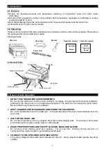
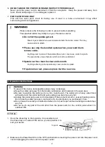
3. Place the required amount of solder into the solder bath and turn the unit ON. Ideal solder level is
5mm below the rim of the bath.
4. Following the Control Panel setting procedure, input the temperature settings. This unit is set to
270 °C (518°F) prior to shipment.
5. When the settings are completed the Output Lamp (ot1) will light and temperature control begins. The
solder will melt in 7~8 minutes so put the solder into the pot little by little until it reaches the right level.
When the measured temperature (PV) and the set temperature (SP) are the same, the Output Lamp
(ot1) will flash and the temperature will be stable. The solder will be melted and work can begin
approximately 20 minutes after starting the temperature control. Before dipping, remove the oxidized
solder dross with the spatula and make sure the solder surface is clean.
6. Turn the unit OFF when not in use or when you are away from it.
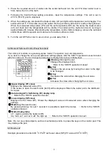
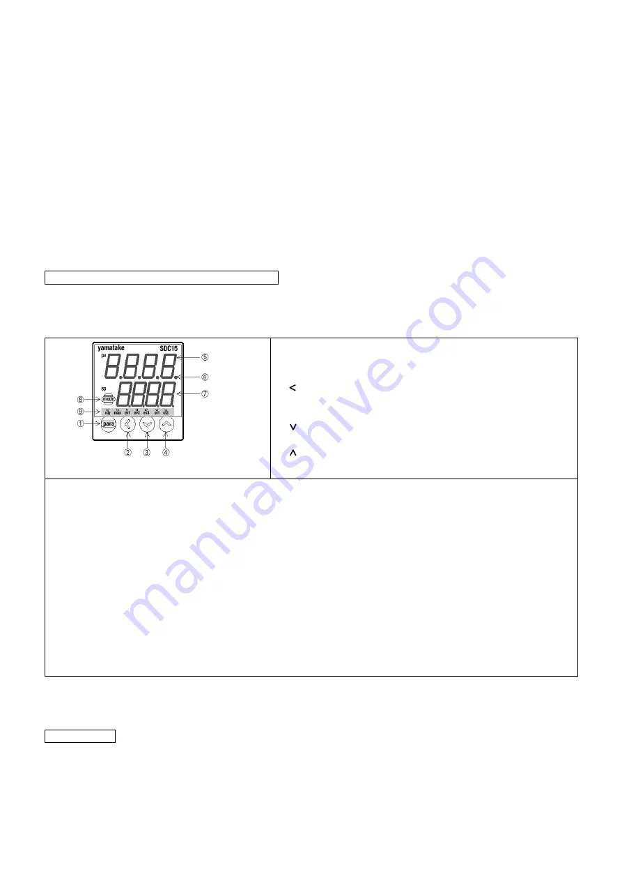
4.2 Name of Parts and Control Panel Functions
The solder pot controller is a general-purpose model. The operator only sets temperature.
If you want to change the set up and parameter settings please refer the SDC15 operation manual included
with this solder pot. You can change the temperature display from Celsius to Fahrenheit.
①
Para key
(No need to use)
Changes the displayed item.
→
Refer to the
‘SDC15 operation manual’.
②
key
Changes the set value by moving the cursor to the digit
to be changed.
③
key
Decreases the value when changing the set value.
④
key
Increases the value when changing the set value.
⑤
Upper display (PV value)
Displays the measured value (PV).
If the sensor is open, the alarm code [AL03] will be displayed. Return the solder pot to the distributor
for repair.
⑥
Auto-tuning (AT) / Self-tuning (ST) display lamp
→
Refer to the
‘SDC15 operation manual’.
⑦
Lower display (SP value)
Displays the Set Value (SP). Shows the displayed value and measured value when changing the
settings.
⑧
Mode key
(No need to use)
By pressing this key for over 1 second it is possible to switch the modes.
→
Refer to the
‘SDC15
operation manual
’.
⑨
Mode display lamp
ot1 : Lights up while the heater is ON.
rdy, man, ev1, ev2, ev3, ot2 : No light up
→
Refer to
the ‘SDC15 operation manual’.
Note : Do not use sharp objects, such as mechanical pencils, to press the keys on the control pad. This
may damage the pad.
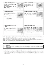
4.3 How to set
Example procedure to enter 400
o
C /752
o
F as the set value (SP) (PV value at 30
o
C/ 86
o
F)


