
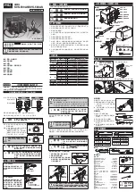
CAUTION
To reship, re-affix the screws
to their original positions.
Ensure that the two screws on
the bottom surface (for break-
age prevention during trans-
port) are removed before use.
5-1.
Assemble the soldering iron
stand following the instructions
on its box.
SVS
-58
0AS
HEATER
1
0
HEATER
1
0
250
350
450
400
300
HEAT
TEMP[C]
200
480
350
300
250
450
TEMP[C]
HEAT
SVS-580AS
SO
LD
ER
ING
IR
ON
DE
SO
LD
ER
ING
GU
N
SER
VIC
E S
TA
TIO
N
MAIN
POWER
1
0
DE
SO
LD
ER
ING
IRO
N
IRO
N
VA
CU
UM
SO
LD
ER
ING
SERVICE STATION
SVS-500AS
/
SVS-580AS
Some smoke will be produced from the
desoldering gun during initial operation,
but it will soon stop. No smoke
produced after the initial operation.
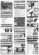
4. PACKAGE CONTENTS / NAMES OF PARTS
5. SETTING
6.
OPERATION
8. REPLACEMENT PARTS
WARNING
WARNING
WARNING
WARNING
5-3.
Place the cleaning pin into its holder,
provided at the rear right side of the
control box.
5-4.
Connect the desolder-
ing gun & soldering
iron to the control box.
(ex.)
SVS-500AS
5-8.
Turn the main power switch ON (to I
side). Turn the power switch for desol-
dering gun and/or soldering iron ON (to
I side). The [
HEAT
] lamp will light up and
the heater will start heating up. When
the [
HEAT
] lamp flashes the machine is
ready to use. (approx. 2-3
mins)
5-6.
Check that the main power switch on the control box is OFF (
side) and
then plug in the control box.
5-7.
Set the desired temperature using the
temperature setting knob.
Ensure that the unit is properly grounded to avoid
electrical shock. The desoldering gun & the solder-
ing iron are conductive.
Never touch the nozzle, tip, or other metal / plastic part.
These areas get very hot. Possibly resulting in serious
personal injury or damage. Be sure that the nozzle / tip has
sufficiently cooled down when storing.
Use this desolder-
ing gun exclusively
to prevent the injury
or damage.
To prevent fire or personal injury, turn off and unplug the
desoldering station if there is a burning smell, overheating,
or if the plastic parts deform. Do not use it again and con-
tact your nearest distributor.
■
TIP
■ステーション部
■こて台 ■取扱説明書
HE
ATER
1
0
HEA
TER
1
0
250
350
450
400
300
HEA
T
TEMP[C]
20
0
480
350
300
250
450
TEMP[C]
HE
AT
SVS
-58
0AS
SO
LD
ER
IN
G
IR
ON
DE
SO
LD
ER
IN
G
GU
N
SE
RV
IC
E S
TA
TIO
N
MAIN
POWER
1
0
DE
SO
LD
ER
IN
G
IR
ON
VA
CU
UM
IR
ON
SO
LD
ER
IN
G
Power Supply Connector for
Desoldering Gun
Vacuum Hose Connector
Power Supply Connector for
Soldering Iron
Power Switch for
Soldering Iron
Power Switch for
Desoldering Gun
Main Power Switch
Temperature Setting Knob for
Desoldering Gun
Heat Lamp for Soldering Iron
Temperature Setting Knob for
Soldering Iron
250V 4A
100V AC
Fuse Holder
Slider
Cartridge
Nozzle
Trigger
Collar
Heater Barrel
Tip
Heat Lamp for
Desoldering Gun
Desoldering
Gun Holster
Cleaning Pin Holder
Felt A
Felt B Steel Wool
(
TP-100CP1.3
in
SVS-580AS
)
Felt A
Felt B Steel Wool
(
TP-100CP1.3
in
SVS-580AS
)
■
Cleaning Pin TP-100CP0.7
■
Soldering Iron Stand ST-76
■
Operation Manual
■
Filter Set TP-100F
NOTE
MODEL
SVS-500AS
SVS-580AS
Voltage
110V, 120-130V, 220-240V AC 50/60Hz
Power Consumption
110V, 120-130V(200W), 220-240V(270-300W)
Temp. Setting Range
Desoldering Gun
250−450˚C (482-842˚F)
Soldering Iron
200−480˚C (392-896˚F)
Heater
Ceramic heater with internal sensor
Temperature Control System
Sensor feedback (ON-OFF control)
Insulation Resistance
Over 100M
Ω
Vacuum Pump System
Diaphragm system
Ultimate Pressure
- 0.08MPa (-600mmHg)
Dimensions
Control Box
205
(
W
)
×160
(
L
)
×170
(
H
)
mm
Desoldering Gun
220×155mm
Soldering Iron
190mm
Weight
Control Box
Approx.3.6kg (w/o cord, hose)
Desoldering Gun
250g (w/o cord)
Soldering Iron
70g
Total
Approx. 4.0kg
Leak Voltage
Less than 2mV
Ground/Earth Resistance
Less than 2
Ω
Connecting cord length
1.2m
Power cord length
3-prong cord 1.5m
SVS-580AS
5-2.
Attach the desoldering gun hol-
ster.
Fuse: 250V 4A
■
Desoldering Gun
■
Soldering Iron
■
Control Box
SOLDERING
IRON
DESOLDERING
IRON
VACUUM
OPEN
350
450
250
400
300
(572)
(752)
(842)
(482)
(662)
HEAT
350
480
250
400
300
(572)
(752)
(896)
450
(842)
(482)
200
(392)
(662)
HEAT
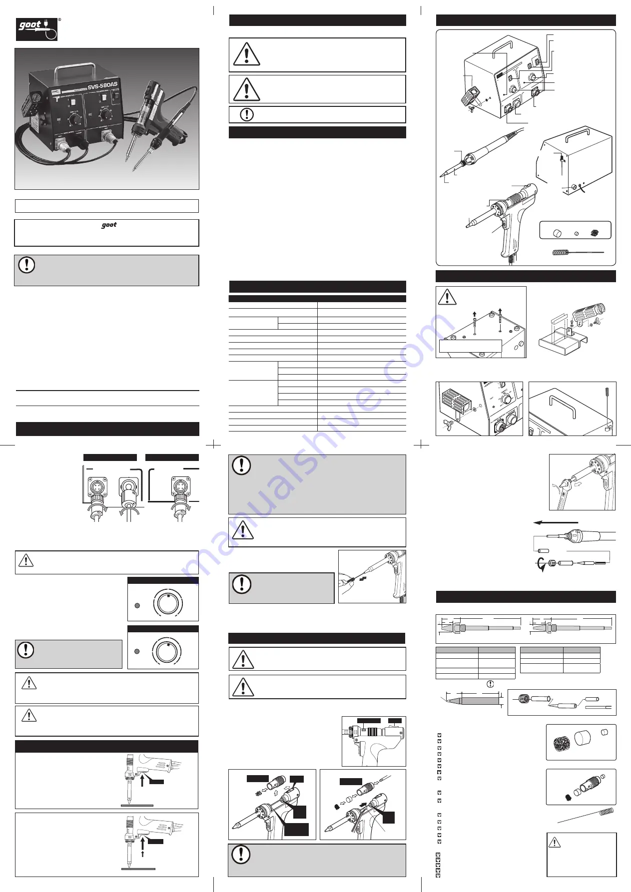
REPLACEMENT OF TIP
1.
Remove the collar by turning it in a
counter-clockwise direction.
2.
Pull out the heater barrel, then pull
out the tip from the heater.
3.
Be sure that the leaf spring (a rolled
metal spring normally stuck inside
the tip) is not stuck to the heater.
4.
Reassemble with new tip, reversing these steps.
5-5.
Put the desoldering gun into its holster, and the soldering iron into its stand.
Desoldering Gun
Desoldering Gun
Soldering Iron
Soldering Iron
Tip
Spacer
Heater
Heater Barrel
Collar
Standard
37
R0.3
φ
7
15
15
36
37.5
φ
8
1.2
φ
3
37
15
φ
7
37
16
φ
5
φ
7
37
15
φ
7
R0.5
φ
5
37
16
φ
7
1
φ
7
φ
5
37
15
37
15
2
φ
5
φ
7
37
15
φ
2.1
φ
7
37
15
φ
7
1
0.5
φ
7
φ
4
37
15
PX-2RT-SB
PX-2RT-6E
PX-2RT-5D
PX-2RT-2C
φ
7
φ
2.4
37
15
0.5
PX-2RT-2.4D
φ
7
φ
1.6
37
15
0.5
PX-2RT-1.6D
PX-2RT-3C
PX-2RT-B
PX-2RT-5K
φ
7
φ
3.2
37
15
0.5
PX-2RT-3.2D
PX-2RT-8S
PX-2RT-5C
PX-2RT-BC
PX-2RT-4D
φ
4
37
15
φ
7
PX-2RT-4C
全周はんだメッキ仕様
全周はんだメッキ仕様(C型)
標準タイプ(C型)
φ
3
37
15
φ
7
φ
5
37
16
φ
7
37
15
φ
2.1
φ
7
PX-2RT-2CR
PX-2RT-3CR
PX-2RT-5CR
φ
4
37
15
φ
7
PX-2RT-4CR
Please refer to our website about other replacement tips.
WARNING
CAUTION
NOTE
Failure to obey a safety warning could result in
serious injury or death to yourself or to others, or
in physical damage.
Failure to obey a safety warning could result in
injury to yourself or to others, or in physical damage.
A note or word of advice.
In this manual, the following safety marks are used.
This is a common operation manual for
SVS-500AS
&
SVS-580AS
. Each model number is mentioned in the text.
Be sure to read properly for your model.
1. SAFETY MARK DEFINITIONS
2. FOR SAFE OPERATION
3. SPECIFICATIONS
1. Do not use in dangerous environments. Never use it in damp, humid
or wet locations (including outside), or near flammable substances.
2. Keep children and bystanders away from the unit.
3. Turn off the power when not in use.
4. Your desoldering station is an electrical tool used to remove solder in
order to free components from printed circuit boards. Do not use this
for any other purpose.
5. Wear proper apparel and safety glasses.
6. Connect to a correct AC power supply. Do not use with any power
voltage other than the indicated voltage.
7. If the power cord, desoldering-gun cord, or soldering-iron cord is
damaged, stop using immediately and turn off the power. Return to
the distributor for replacement.
8. Be sure to use the ST-76 soldering iron stand included with this
Soldering station. Other soldering iron stands may melt the parts of this
unit.
9. Make sure that the machine must be grounded at all times to prevent
electrical shocks and static electricity.
1. SAFETY MARK DEFINITIONS
2. FOR SAFE OPERATION
3. SPECIFICATIONS
4. PACKAGE CONTENTS / NAME OF PARTS
5. SETTING
6. OPERATION
7. MAINTENANCE
8. REPLACEMENT PARTS
TAIYO ELECTRIC IND.CO.,LTD.
KEEP THIS MANUAL FOR FUTURE REFERENCE
Thank you for buying the
Service Station. Read
this Owner’s Operation Manual before using your
service station.
NOTE
www.goot.co.jp
E-mail:
info@goot.co.jp
OPERATION MANUAL
7. MAINTENANCE
SVS-500AS
Place the nozzle over the leads of the
component to be removed. Wait until
the solder melts, then pull the trigger for
desoldering.
SVS-580AS
Place the nozzle over the leads of the
component to be removed. Wait until the
solder melts, then pull the trigger slightly.
The pump starts operating, and the vacuum
is created in the vacuum chamber. Next, pull
the trigger more. The open-valve will open,
and the solder is pumped.
After desoldering operation, remove any solder
scraps on the nozzle by the wetted heat-
resistant sponge on the soldering iron stand.
When operation is completed, push in and pull out the cleaning pin 3 or 4
times (to reduce nozzle clogs). Lastly, do not fail to put the pretinning on the
nozzle tip (to prevent oxidation of the nozzle tip).
REPLACEMENT OF NOZZLE
When the clogged collected solder in the nozzle
cannot be removed by the cleaning pin or
cleaning drill, the nozzle needs to be replaced.
1.
Turn the nozzle counterclockwise using a
wrench (11mm) and remove it.
2.
Replace with a new nozzle. Be careful not to
overtighten it.
1.
Pull back the slider and take out the cartridge.
2.
Remove the solder scraps from the cartridge.
3.
Connect the arrow side of the cartridge to the
front ring gasket. Return the slider to the front.
Make sure that the rear plug goes into the
cartridge.
Arrow Mark
Slider
Tweezers
Steel
Wool
Felt A
Felt B
Screwdriver
Cartridge
Rear
Plug
Collected
Solder Scrap
Front Ring
Gasket
Rear
Plug
Slider
Cartridge
Overall View
(Standard Type)
Overall View
(Slim Type)
20
20
77.5
77.5
12
φ
8.0
φ
6.4
14
Filter Set TP-100F
Cartridge Set TP-100K
Cleaning Pin
■
NOZZLE
Part NO.
Gauge
TP-100N-08
φ
0.8mm
TP-100N-10
(
SVS-500AS
Standard
)
φ
1.0mm
TP-100N-15
φ
1.5mm
TP-100N-25
φ
2.5mm
Part NO.
Gauge
TP-100N-S8
φ
0.8mm
TP-100N-S1
φ
1.0mm
TP-100N-S5
(
SVS-580AS
Standard
)
φ
1.5mm
Felt A
Felt B
Steel Wool
Steel
Wool
Felt A
Felt B
Cartridge
(1pcs)
(3pcs)
Trigger
Trigger
Pull trigger when solder melts.
1. Place against the leads,
and pull trigger slightly.
2. When solder has melted,
pull trigger fully.
Trigger
Trigger
Pull trigger when solder melts.
1. Place against the leads,
and pull trigger slightly.
2. When solder has melted,
pull trigger fully.
Turn off the main power switch (to
side),
unplug the power cord before maintenance.
And be sure that the nozzle / tip is cooled down.
Use only genuine goot replacement parts for
maintenance. The use of any other parts may
be hazardous and cause damage to the unit.
Do not pull the trigger for more than 2 seconds.
Wait at least 10 seconds between trigger pulls.
Failure to do so could result in the heater or
motor overheating.
SVS-500AS
After releasing the trigger, the pump will operate
for approx. 0.5 seconds more, to pump the collected solder in the
nozzle.
SVS-580AS
When the vacuum chamber is completely filled,
the pump cannot take effect even if the trigger is pulled. In that
case, pull the trigger in completely. The open-valve will open, and
restore negative pressure in the chamber. Then the pump will
operate again.
Clean the nozzle with the cleaning
pin frequently during desoldering
work. A cleaning drill is an optional
part for some nozzle sizes.
NOTE
NOTE
WARNING
CAUTION
CAUTION
CLEANING AND REPLACEMENT OF CARTRIDGE, FILTER
■
REPLACEMENT PARTS
Cleaning Pin
Cleaning Pin Vice
(Option)
Soldering Iron
Exclusive for
SVS-500AS
......
TP-20GAS
Heater
..................................
TP-100H
Exclusive for
SVS-580AS
......
TP-28GAS
Heater barrel
.....................
TP-100HP
Desoldering Gun
φ
0.7mm
(for
φ
0.8 & 1.0mm nozzle)
.......
TP-100CP 0.7
Pin vice body (The drill bit is not included.) ..............
TP-100PV
φ
1.3mm (for
φ
1.5 & 2.5mm nozzle) ..........
TP-100CP 1.3
Drill Bit
φ
0.7mm......................................
TP-100DB-07
Drill Bit
φ
0.9mm......................................
TP-100DB-09
Drill Bit
φ
1.4mm......................................
TP-100DB-14
Drill Bit
φ
2.4mm......................................
TP-100DB-24
Heater
....................................................................
SVS-500H-1
Heater barrel
...........................................................
TQ-77HP
Spacer
......................................................................
TQ-77SS
Collar
........................................................................
TQ-77NUT
Soldering iron unit
(common for
SVS-500
/
580
) ....
SVS-50GAS
Filter Set (3pcs)
.............
TP-100F
Felt B (10pcs)
................
TP-100RFT
Cartridge Set
................
TP-100K
Steel Wool Only
............
TP-100UL
Do not use this desoldering gun without both felt A and felt B.
The pump could be damaged.
SVS-580AS
: The powerful suction
makes many more filter clogs than
SVS-500AS
. Requires frequent
replacing of the filter to maintain desoldering power.
NOTE
Tip Spring
Spacer
Heater
Heater
Barrel
Collar
Printed in Japan, MAY 2013 A4610AH01


