3B.12
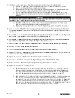
Connect the Remote Mount Coil Cord Extension cable from the Remote Mount Handle to the Remote Mount
Coil Cord. Connect the Float Mode Extension cable from the Remote Mount Handle to the Remote
Mounted Load Cell assembly. Securely clamp the Remote Mount Coil Cord Extension and Float Mode
Extension cable to the tooling as needed (
reference Figure I4
, page 68).
STEP 4 - INSTALLING THE ACTUATOR ASSEMBLY
4.1
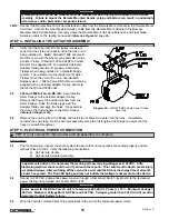
Verify that the G-Force® BX ILD trolley wheels are
correct for the style and capacity track that the unit is
being installed on.
Note:
Standard 150# G-Force®
BX ILDs come with the wheels pre-assembled to the
Actuator Trolley. Standard 300 and 380# G-Force®
BX ILDs are supplied with an assembled Actuator
Adapter Trolley and two (2) properly sized Hoist
Trolleys when being installed in a Gorbel® Bridge
system. The customer must provide two (2) Hoist
Trolleys when the unit will run in a non-Gorbel®
Bridge system. 150# G-Force® BX ILDs can also be
supplied with an Actuator Adapter Trolley, similar to
that of the 300 and 380# units.
4.2
300 and 380# G-Force® BX ILD:
Assemble the
Hoist Trolleys to the Actuator Adapter Trolley.
Remove the Clevis Pin and flat washers from the
Hoist Trolleys. Slide the Trolley legs over the
Adapter Trolley and align the holes. Re-assemble
the Clevis Pin and washers to the Hoist Trolleys
(
reference Diagram 4A
).
4.3
Remove the end stop from the Bridge and install the G-Force® Actuator into the track. Immediately
re-install the end stops. Roll the Actuator assembly along the full length of the Bridge to assure that the
travel is smooth throughout.
STEP 5 - ELECTRICAL POWER CONNECTION
STANDARD:
5.1
Prior to final wiring, inspect the entire system to assure that all connections are seated properly and are
without kinks or bends. Verify the following connections:
a) Coil Cord to Handle
b) Coil Cord to Actuator Assembly
5.2
Connect a 220 VAC single-phase power source through a Disconnect Switch (by others) to the festooned
power cabling (not provided with G-Force® BX ILD).
5.3
Wire the Female Turnlock Power Plug (provided) to the end of the festooned power cable.
WARNING
Remote Mount G-Force® BX Handles must be mounted at both the top and bottom of the Handle
assembly. Failure to mount the Remote Mounted Handle at top and bottom can result in undesirable
performance and/or premature component failure.
Diagram 4A.
300/380# BX Actuator-Hoist Trolley
Assembly.
15
4/04-Rev. S
TIP:
Do not connect to main power until all assembly is complete.
WARNING
Source power to the BX G-Force® unit is to measure 220 VAC (1 Phase) +/- 10%. Minimum Voltage =
198 VAC. Maximum Voltage Must NOT Exceed 242 VAC. Voltages greater than 242 VAC will result in
premature Control System failure.
WARNING
To operate servo drives, it is necessary that certain parts are carrying voltages over 42 VDC. A life-
threatening electrical shock could occur if you touch these parts. This could result in death, severe injury
or material damage. After switching off the servo drive, wait until the DC bus discharge time of at least 5
minutes has passed. The Run LED going out does not indicate that voltage is not present on the device.
®
Summary of Contents for 150 BX G-Force
Page 26: ...Figure A3 bottom Figure A4 top 150 BX Actuator Assembly 25 4 04 Rev S ...
Page 27: ...Figure A5 150 BX Actuator Assembly 26 4 04 Rev S ...
Page 28: ...Figure A6 150 BX Actuator Assembly 27 4 04 Rev S ...
Page 29: ...Figure A7 bottom Figure A8 top 150 BX Actuator Assembly 28 4 04 Rev S ...
Page 30: ...Figure A9 bottom Figure A10 top 150 BX Actuator Assembly 29 4 04 Rev S ...
Page 31: ...Figure A11 bottom Figure A12 top 150 BX Actuator Assembly 30 4 04 Rev S ...
Page 32: ...Figure A13 150 BX Actuator Assembly 31 4 04 Rev S ...
Page 33: ...Figure A14 150 BX Actuator Assembly 32 4 04 Rev S ...
Page 35: ...Figure B3 bottom Figure B4 top 300 380 BX Actuator Assembly 34 4 04 Rev S ...
Page 36: ...Figure B5 300 380 BX Actuator Assembly 35 4 04 Rev S ...
Page 37: ...Figure B6 300 380 BX Actuator Assembly 36 4 04 Rev S ...
Page 38: ...Figure B7 bottom Figure B8 top 300 380 BX Actuator Assembly 37 4 04 Rev S ...
Page 39: ...Figure B9 bottom Figure B10 top 300 380 BX Actuator Assembly 38 4 04 Rev S ...
Page 40: ...Figure B11 bottom Figure B12 top 300 380 BX Actuator Assembly 39 4 04 Rev S ...
Page 41: ...40 Figure B13 300 380 BX Actuator Assembly 4 04 Rev S ...
Page 42: ...Figure B14 300 380 BX Actuator Assembly 41 4 04 Rev S ...
Page 44: ...Figure C3 Standard Handle Assembly 43 4 04 Rev S ...
Page 45: ...Figure C4 Standard Handle Assembly 44 4 04 Rev S ...
Page 46: ...Figure C5 bottom Figure C6 top Standard Handle Assembly 45 4 04 Rev S ...
Page 47: ...Figure C7 bottom Figure C8 top Standard Handle Assembly 46 4 04 Rev S ...
Page 48: ...Figure C9 bottom Figure C10 top Standard Handle Assembly 47 4 04 Rev S ...
Page 49: ...Figure C11 bottom Figure C12 top Standard Handle Assembly 48 4 04 Rev S ...
Page 50: ...Figure C13 Standard Handle Assembly 49 4 04 Rev S ...
Page 52: ...Figure D3 bottom Figure D4 top Float Mode Handle Assembly 51 4 04 Rev S ...
Page 53: ...Figure D5 bottom Figure D6 top Float Mode Handle Assembly 52 4 04 Rev S ...
Page 54: ...Figure D7 bottom Figure D8 top Float Mode Handle Assembly 53 4 04 Rev S ...
Page 55: ...Figure D9 bottom Figure D10 top Float Mode Handle Assembly 54 4 04 Rev S ...
Page 56: ...Figure D11 Float Mode Handle Assembly 55 4 04 Rev S ...
Page 58: ...Figure E2 Air Coil Cord Assembly Standard Float Mode 57 4 04 Rev S ...
Page 59: ...Figure E3 Remote Mount Coil Cord Standard Float Mode 58 4 04 Rev S ...
Page 60: ...Figure E4 Air Remote Mount Coil Cord Standard Float Mode 59 4 04 Rev S ...
Page 61: ...APPENDIX F CONTROLS SCHEMATIC DRAWINGS Figure F1 Remote Load Cell Assembly 60 4 04 Rev S ...
Page 62: ...Figure F2 BX Controls Schematic 61 4 04 Rev S ...
Page 64: ...Figure G2 BX G Force 300 380 Overall Dimensions 63 4 04 Rev S ...
Page 67: ...Figure I2 300 380 Standard Inline Component Layout 66 4 04 Rev S ...
Page 68: ...Figure I3 Standard Remote Mount Component Layout 67 4 04 Rev S ...

