8.2
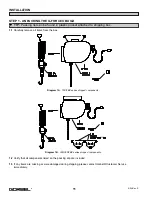
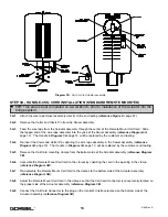
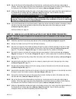
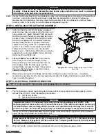
Using a small flat-head screwdriver, the position of the switch can be turned to any of the positions that are
numbered from 0 to 9. If a slower speed is desired, position the switch to a smaller number (towards 0). If a
faster speed is desired, position the switch to a larger number (towards 9).
STEP 9 - FLOAT MODE (OPTION)
9.1
Lift and steady the load.
9.2
Without applying any external forces to the load, press the Float Mode Button for one (1) second. When done
correctly, the “Blue” LED light will turn on (the “Yellow” LED will remain on as well).
9.3
The direction and speed of travel is now being controlled by the amount of force that the operator exerts directly
onto the load. To move the load down, put vertical pressure on the load in down direction. To move the load up,
lift up on the load in the vertical up direction. The higher the force exerted on the load, the faster the unit
moves.
STEP 10 - FINAL STEPS
10.1
Please contact the Gorbel® factory (585-924-6262) of any of the following occur.
DO NOT ATTEMPT TO
REPAIR UNIT YOURSELF.
•
Excessive noise
•
Unexpected operation
•
Change in performance
•
Damage or excessive wear to unit components
•
Questions about the unit arise
Please do not be limited by these items only.
10.2
Keep Packing List, Installation Manual, Drawings, and any other inserts filed together in a safe place.
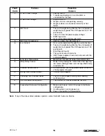
DRIVE FAULT TROUBLESHOOTING CHART
The G-Force® ILD has extensive diagnostic capability. The “Red” System Fault LED flashes when basic faults have
been detected by the control system. If a fault has occurred, the Standard Mode Operating or Float Mode LEDs will
go off.
The red System Fault LED flashes a simple code when a fault has occurred. The sequence of flashes indicates the
type of fault. The sequence consists of a number of short flashes followed by a long pause. The number of short
flashes is the key to determining the fault code. For example, three (3) short flashes followed by a long pause
indicates fault code #3. The sequence continually repeats until the fault is reset. The Fault Codes are listed in the
chart on the next page.
WARNING
If external forces are applied to the load while Float Mode is being initiated, the G-Force® will calculate
a baseline weight that is higher or lower than the actual weight being lifted. When the external force is
removed, the load will begin to drift in the opposite direction of the load that was applied.
WARNING
NEVER remove the load from the G-Force® while still in Float Mode. The drive will interpret the removal
of the load as operator intent to lift the load. Therefore, the Handle will begin to drift up. The speed of
the Handle drift directly correlates to the weight that was removed from the unit. The heavier the
weight, the faster the Handle will travel.
TIP:
Gorbel® Customer Service is available from 7am to 7pm Eastern Time Monday -
Thursday and 7am to 5pm Eastern Time Friday.
17
4/04-Rev. S
®
Summary of Contents for 150 BX G-Force
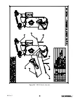
Page 26: ...Figure A3 bottom Figure A4 top 150 BX Actuator Assembly 25 4 04 Rev S ...
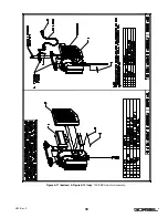
Page 27: ...Figure A5 150 BX Actuator Assembly 26 4 04 Rev S ...
Page 28: ...Figure A6 150 BX Actuator Assembly 27 4 04 Rev S ...
Page 29: ...Figure A7 bottom Figure A8 top 150 BX Actuator Assembly 28 4 04 Rev S ...
Page 30: ...Figure A9 bottom Figure A10 top 150 BX Actuator Assembly 29 4 04 Rev S ...
Page 31: ...Figure A11 bottom Figure A12 top 150 BX Actuator Assembly 30 4 04 Rev S ...
Page 32: ...Figure A13 150 BX Actuator Assembly 31 4 04 Rev S ...
Page 33: ...Figure A14 150 BX Actuator Assembly 32 4 04 Rev S ...
Page 35: ...Figure B3 bottom Figure B4 top 300 380 BX Actuator Assembly 34 4 04 Rev S ...
Page 36: ...Figure B5 300 380 BX Actuator Assembly 35 4 04 Rev S ...
Page 37: ...Figure B6 300 380 BX Actuator Assembly 36 4 04 Rev S ...
Page 38: ...Figure B7 bottom Figure B8 top 300 380 BX Actuator Assembly 37 4 04 Rev S ...
Page 39: ...Figure B9 bottom Figure B10 top 300 380 BX Actuator Assembly 38 4 04 Rev S ...
Page 40: ...Figure B11 bottom Figure B12 top 300 380 BX Actuator Assembly 39 4 04 Rev S ...
Page 41: ...40 Figure B13 300 380 BX Actuator Assembly 4 04 Rev S ...
Page 42: ...Figure B14 300 380 BX Actuator Assembly 41 4 04 Rev S ...
Page 44: ...Figure C3 Standard Handle Assembly 43 4 04 Rev S ...
Page 45: ...Figure C4 Standard Handle Assembly 44 4 04 Rev S ...
Page 46: ...Figure C5 bottom Figure C6 top Standard Handle Assembly 45 4 04 Rev S ...
Page 47: ...Figure C7 bottom Figure C8 top Standard Handle Assembly 46 4 04 Rev S ...
Page 48: ...Figure C9 bottom Figure C10 top Standard Handle Assembly 47 4 04 Rev S ...
Page 49: ...Figure C11 bottom Figure C12 top Standard Handle Assembly 48 4 04 Rev S ...
Page 50: ...Figure C13 Standard Handle Assembly 49 4 04 Rev S ...
Page 52: ...Figure D3 bottom Figure D4 top Float Mode Handle Assembly 51 4 04 Rev S ...
Page 53: ...Figure D5 bottom Figure D6 top Float Mode Handle Assembly 52 4 04 Rev S ...
Page 54: ...Figure D7 bottom Figure D8 top Float Mode Handle Assembly 53 4 04 Rev S ...
Page 55: ...Figure D9 bottom Figure D10 top Float Mode Handle Assembly 54 4 04 Rev S ...
Page 56: ...Figure D11 Float Mode Handle Assembly 55 4 04 Rev S ...
Page 58: ...Figure E2 Air Coil Cord Assembly Standard Float Mode 57 4 04 Rev S ...
Page 59: ...Figure E3 Remote Mount Coil Cord Standard Float Mode 58 4 04 Rev S ...
Page 60: ...Figure E4 Air Remote Mount Coil Cord Standard Float Mode 59 4 04 Rev S ...
Page 61: ...APPENDIX F CONTROLS SCHEMATIC DRAWINGS Figure F1 Remote Load Cell Assembly 60 4 04 Rev S ...
Page 62: ...Figure F2 BX Controls Schematic 61 4 04 Rev S ...
Page 64: ...Figure G2 BX G Force 300 380 Overall Dimensions 63 4 04 Rev S ...
Page 67: ...Figure I2 300 380 Standard Inline Component Layout 66 4 04 Rev S ...
Page 68: ...Figure I3 Standard Remote Mount Component Layout 67 4 04 Rev S ...

