WIRE ROPE INSPECTION
1) Frequent Inspection
The operator or other designated person should visually inspect all ropes at the start of each shift. These visual
observations should be concerned with discovering gross damage, such as listed below, which may be an
immediate hazard:
(a) distortion of the rope such as kinking, crushing, unstranding, birdcaging, main strand displacement, or
core protrusion;
(b) general corrosion;
(c) broken or cut strands;
(d) number, distribution, and type of visible broken wires. [See next section on rope replacement]
When such damage is discovered, the rope shall either be removed from service or given an inspection as
detailed in the next section.
2) Periodic Inspection
The inspection frequency shall be determined by a qualified person and shall be based on such factors as
expected rope life as determined by experience on the particular installation or similar installations; severity of
environment; percentage of capacity lifts; frequency rates of operation; and exposure to shock loads.
Inspections need not be at equal calendar intervals and should be more frequent as the rope approaches the
end of its useful life.
A designated person shall perform periodic inspections. This inspection shall cover the entire length of rope.
The individual outer wires in the strands of the rope shall be visible to this person during the inspection. Any
deterioration resulting in appreciable loss of original strength, such as described below, shall be noted, and
determination shall be made as to whether further use of the rope would constitute a hazard:
(a) points listed in previous section on frequent inspection;
(b) reduction of rope diameter below nominal diameter due to loss of core support, internal or external
corrosion, or wear of outside wires;
(c) severely corroded or broken wires at end connections;
(d) severely corroded, cracked, bent, worn, or improperly applied end connections.
Special care should be taken when inspection sections of rapid deterioration, such as the following:
(a) sections in contact with saddles, equalizer sheaves, or other sheaves where rope travel is limited;
(b) sections of rope at or near terminal ends where corroded or broken wires may protrude;
(c) sections subject to reverse bends;
(d) sections of ropes that are normally hidden during visual inspection, such as parts passing over sheaves.
WIRE ROPE MAINTENANCE
1) Rope should be stored to prevent damage or deterioration.
2) Rope shall be unreeled or uncoiled in a manner to avoid kinking of or inducing a twist in the rope.
3) Before cutting rope, means shall be used to prevent unlaying of the strands.
4) During installation, care should be observed to avoid dragging of the rope in dirt or around objects that will
scrape, nick, crush, or induce sharp bends.
19
4/04-Rev. S
®
Summary of Contents for 150 BX G-Force
Page 26: ...Figure A3 bottom Figure A4 top 150 BX Actuator Assembly 25 4 04 Rev S ...
Page 27: ...Figure A5 150 BX Actuator Assembly 26 4 04 Rev S ...
Page 28: ...Figure A6 150 BX Actuator Assembly 27 4 04 Rev S ...
Page 29: ...Figure A7 bottom Figure A8 top 150 BX Actuator Assembly 28 4 04 Rev S ...
Page 30: ...Figure A9 bottom Figure A10 top 150 BX Actuator Assembly 29 4 04 Rev S ...
Page 31: ...Figure A11 bottom Figure A12 top 150 BX Actuator Assembly 30 4 04 Rev S ...
Page 32: ...Figure A13 150 BX Actuator Assembly 31 4 04 Rev S ...
Page 33: ...Figure A14 150 BX Actuator Assembly 32 4 04 Rev S ...
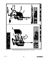
Page 35: ...Figure B3 bottom Figure B4 top 300 380 BX Actuator Assembly 34 4 04 Rev S ...
Page 36: ...Figure B5 300 380 BX Actuator Assembly 35 4 04 Rev S ...
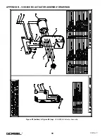
Page 37: ...Figure B6 300 380 BX Actuator Assembly 36 4 04 Rev S ...
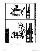
Page 38: ...Figure B7 bottom Figure B8 top 300 380 BX Actuator Assembly 37 4 04 Rev S ...
Page 39: ...Figure B9 bottom Figure B10 top 300 380 BX Actuator Assembly 38 4 04 Rev S ...
Page 40: ...Figure B11 bottom Figure B12 top 300 380 BX Actuator Assembly 39 4 04 Rev S ...
Page 41: ...40 Figure B13 300 380 BX Actuator Assembly 4 04 Rev S ...
Page 42: ...Figure B14 300 380 BX Actuator Assembly 41 4 04 Rev S ...
Page 44: ...Figure C3 Standard Handle Assembly 43 4 04 Rev S ...
Page 45: ...Figure C4 Standard Handle Assembly 44 4 04 Rev S ...
Page 46: ...Figure C5 bottom Figure C6 top Standard Handle Assembly 45 4 04 Rev S ...
Page 47: ...Figure C7 bottom Figure C8 top Standard Handle Assembly 46 4 04 Rev S ...
Page 48: ...Figure C9 bottom Figure C10 top Standard Handle Assembly 47 4 04 Rev S ...
Page 49: ...Figure C11 bottom Figure C12 top Standard Handle Assembly 48 4 04 Rev S ...
Page 50: ...Figure C13 Standard Handle Assembly 49 4 04 Rev S ...
Page 52: ...Figure D3 bottom Figure D4 top Float Mode Handle Assembly 51 4 04 Rev S ...
Page 53: ...Figure D5 bottom Figure D6 top Float Mode Handle Assembly 52 4 04 Rev S ...
Page 54: ...Figure D7 bottom Figure D8 top Float Mode Handle Assembly 53 4 04 Rev S ...
Page 55: ...Figure D9 bottom Figure D10 top Float Mode Handle Assembly 54 4 04 Rev S ...
Page 56: ...Figure D11 Float Mode Handle Assembly 55 4 04 Rev S ...
Page 58: ...Figure E2 Air Coil Cord Assembly Standard Float Mode 57 4 04 Rev S ...
Page 59: ...Figure E3 Remote Mount Coil Cord Standard Float Mode 58 4 04 Rev S ...
Page 60: ...Figure E4 Air Remote Mount Coil Cord Standard Float Mode 59 4 04 Rev S ...
Page 61: ...APPENDIX F CONTROLS SCHEMATIC DRAWINGS Figure F1 Remote Load Cell Assembly 60 4 04 Rev S ...
Page 62: ...Figure F2 BX Controls Schematic 61 4 04 Rev S ...
Page 64: ...Figure G2 BX G Force 300 380 Overall Dimensions 63 4 04 Rev S ...
Page 67: ...Figure I2 300 380 Standard Inline Component Layout 66 4 04 Rev S ...
Page 68: ...Figure I3 Standard Remote Mount Component Layout 67 4 04 Rev S ...

