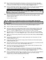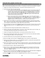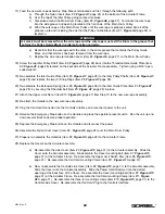
5) Rope should be maintained in a well-lubricated condition. Gorbel recommends using Chain and Cable
Penetrating oil for lubrication. Lubricant applied as part of a maintenance program shall be compatible with the
original lubricant. Lubricant applied shall be of the type that does not hinder visual inspection. Immediately after
inspection, lubricant shall be applied before rope is returned to service. Those sections of rope that are located
over sheaves or otherwise hidden during inspection and maintenance procedures require special attention when
lubricating rope. The object of rope lubrication is to reduce internal friction and to prevent corrosion.
WIRE ROPE REPLACEMENT CRITERIA
1) No precise rules can be given for determination of the exact time for rope replacement, since many factors are
involved. Once a rope reaches any one of the specified removal criteria, it may be allowed to operate to the end of
the work shift, based on the judgement of a qualified person. The rope shall be replaced after that work shift, at the
end of the day, or at the latest time prior to the equipment being used by the next work shift.
2) Removal criteria for the rope replacement shall be as follows:
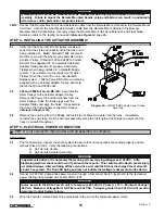
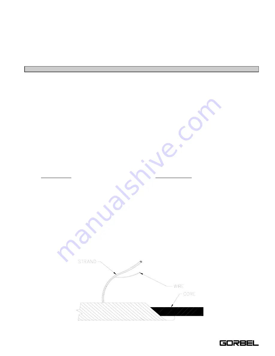
(a) in running ropes, 12 randomly distributed broken wires in one lay or four broken wires in one strand in
one lay (
reference Diagram E below
);
(b) one outer wire broken at the contact point with the core of the rope, which has worked its way out of the
rope structure and protrudes or loops out from the rope structure;
(c) wear of one-third the original diameter of outside individual wires;
(d) kinking, crushing, birdcaging, or any other damage resulting in distortion of the rope structure;
(e) evidence of heat damage from any cause;
(f) reductions from nominal diameter greater than those shown below:
Maximum Allowable
Reduction From
Rope Diameter
Nominal Diameter
Up to 5/16 in. (8 mm)
1/64 in. (0.4 mm)
3) Broken wire removal criteria applies to wire ropes operating on steel sheaves and drums. However, results of
internal testing have shown that rope replacement follows the same criteria regardless of sheave or drum
material.
4) Attention shall be given to end connections. Upon development of two broken wires adjacent to a socketed end
connection, the rope should be resocketed or replaced. Resocketing shall not be attempted if the resulting rope
length will be insufficient for proper operation.
5) Replacement rope and connections shall have strength rating at least as great as the original rope and
connections furnished by the hoist manufacturer. A rope manufacturer, the hoist manufacturer, or a qualified
person shall specify any deviation from the original size, grade, or construction.
Diagram E.
Wire Rope Composition Diagram.
20
4/04-Rev. S
®
Summary of Contents for 150 BX G-Force
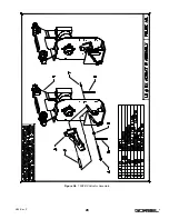
Page 26: ...Figure A3 bottom Figure A4 top 150 BX Actuator Assembly 25 4 04 Rev S ...
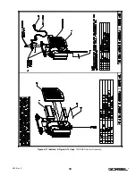
Page 27: ...Figure A5 150 BX Actuator Assembly 26 4 04 Rev S ...
Page 28: ...Figure A6 150 BX Actuator Assembly 27 4 04 Rev S ...
Page 29: ...Figure A7 bottom Figure A8 top 150 BX Actuator Assembly 28 4 04 Rev S ...
Page 30: ...Figure A9 bottom Figure A10 top 150 BX Actuator Assembly 29 4 04 Rev S ...
Page 31: ...Figure A11 bottom Figure A12 top 150 BX Actuator Assembly 30 4 04 Rev S ...
Page 32: ...Figure A13 150 BX Actuator Assembly 31 4 04 Rev S ...
Page 33: ...Figure A14 150 BX Actuator Assembly 32 4 04 Rev S ...
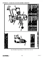
Page 35: ...Figure B3 bottom Figure B4 top 300 380 BX Actuator Assembly 34 4 04 Rev S ...
Page 36: ...Figure B5 300 380 BX Actuator Assembly 35 4 04 Rev S ...
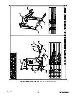
Page 37: ...Figure B6 300 380 BX Actuator Assembly 36 4 04 Rev S ...
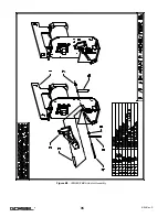
Page 38: ...Figure B7 bottom Figure B8 top 300 380 BX Actuator Assembly 37 4 04 Rev S ...
Page 39: ...Figure B9 bottom Figure B10 top 300 380 BX Actuator Assembly 38 4 04 Rev S ...
Page 40: ...Figure B11 bottom Figure B12 top 300 380 BX Actuator Assembly 39 4 04 Rev S ...
Page 41: ...40 Figure B13 300 380 BX Actuator Assembly 4 04 Rev S ...
Page 42: ...Figure B14 300 380 BX Actuator Assembly 41 4 04 Rev S ...
Page 44: ...Figure C3 Standard Handle Assembly 43 4 04 Rev S ...
Page 45: ...Figure C4 Standard Handle Assembly 44 4 04 Rev S ...
Page 46: ...Figure C5 bottom Figure C6 top Standard Handle Assembly 45 4 04 Rev S ...
Page 47: ...Figure C7 bottom Figure C8 top Standard Handle Assembly 46 4 04 Rev S ...
Page 48: ...Figure C9 bottom Figure C10 top Standard Handle Assembly 47 4 04 Rev S ...
Page 49: ...Figure C11 bottom Figure C12 top Standard Handle Assembly 48 4 04 Rev S ...
Page 50: ...Figure C13 Standard Handle Assembly 49 4 04 Rev S ...
Page 52: ...Figure D3 bottom Figure D4 top Float Mode Handle Assembly 51 4 04 Rev S ...
Page 53: ...Figure D5 bottom Figure D6 top Float Mode Handle Assembly 52 4 04 Rev S ...
Page 54: ...Figure D7 bottom Figure D8 top Float Mode Handle Assembly 53 4 04 Rev S ...
Page 55: ...Figure D9 bottom Figure D10 top Float Mode Handle Assembly 54 4 04 Rev S ...
Page 56: ...Figure D11 Float Mode Handle Assembly 55 4 04 Rev S ...
Page 58: ...Figure E2 Air Coil Cord Assembly Standard Float Mode 57 4 04 Rev S ...
Page 59: ...Figure E3 Remote Mount Coil Cord Standard Float Mode 58 4 04 Rev S ...
Page 60: ...Figure E4 Air Remote Mount Coil Cord Standard Float Mode 59 4 04 Rev S ...
Page 61: ...APPENDIX F CONTROLS SCHEMATIC DRAWINGS Figure F1 Remote Load Cell Assembly 60 4 04 Rev S ...
Page 62: ...Figure F2 BX Controls Schematic 61 4 04 Rev S ...
Page 64: ...Figure G2 BX G Force 300 380 Overall Dimensions 63 4 04 Rev S ...
Page 67: ...Figure I2 300 380 Standard Inline Component Layout 66 4 04 Rev S ...
Page 68: ...Figure I3 Standard Remote Mount Component Layout 67 4 04 Rev S ...


