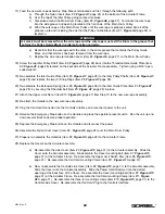
17) Feed the new wire rope assembly, Stop Sleeve terminated end first, through the following path:
a) Through the Nylon Insert (Item #2,
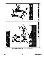
Figure A1
, page 24) at the bottom of the Actuator Frame.
b) Over the top of the Idler Pulley going counter-clockwise.
c)
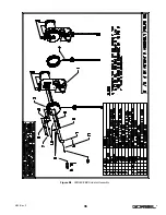
Clockwise around the Main Drum Pulley (Item #2,
Figure A6
, page 27). Terminate the wire rope
into the side groove and opening located at the front side of the Main Drum Pulley.
d) Wind the wire rope on the Main Drum Pulley until the wire rope is properly seated into all of the
grooves up to and including the one that the Pulley Guide Block (Item #1,
Figure A4
, page 25) is
located in.
e) Reconfirm that the wire rope exits the drum in the same groove that contains the Pulley Guide
Block, and that all slack has been removed from the wire rope.
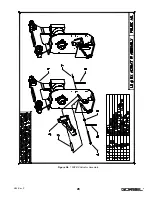
f)
Replace the wire rope termination cover (Item #3,
Figure A6
, page 27) on the Main Drum Pulley.
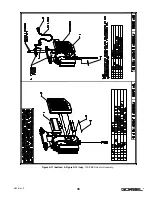
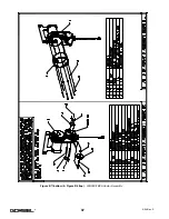
18) Screw the top Idler Pulley Shaft (Item #4,
Figure A7
, page 28) back into the Threaded Hole Guide Plate (Item
#2,
Figure A7
, page 28) located on the backside of the Actuator Frame assembly. Tighten using a 5/16” open-
ended wrench.
19) Re-assemble the Idler Guide Plate (Item #3,
Figure A7
, page 28) to the Idler Pulley Shafts (Item #4,
Figure A7
,
page 28) and replace the two (2) Snap Rings (Item #8,
Figure A7
, page 28).
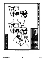
20) Re-assemble the Extension Spring (Item #5,
Figure A5
, page 26) to the Idler Guide Plate (Item #3,
Figure A7
,
page 28), by securing the Shoulder bolt (Item #9,
Figure A7
, page 28) in place.
21) Attach the Upper Limit Donut (Item #10,
Figure A6
, page 27) from Step 10 to the new wire rope assembly.
22) Re-attach the Handle to the new wire rope assembly.
23) Plug the Coil Cord Connector into the Controls Interface and reconnect power to the unit.
24) Release the Emergency Stop button on the Handle and grasp the operator present switch. Run the unit up and
down several times to assure proper operation.
25) Depress the Emergency Stop button on the Handle and disconnect the power.
26) Assemble the Nylon Drum Cover (Item #2,
Figure A8
, page 28) over the Main Drum Pulley.
27) Properly re-assemble the Heatsink (Item #2,
Figure A9
, page 29) to the Actuator Frame.
28) Replace the Covers on the Actuator assembly.
a) Re-assemble the side Cover (Item #3,
Figure A13
, page 31) to the Actuator assembly. Slide the
Cover onto the Actuator assembly. Re-assemble the Cover mounting bolt (Item #7,
Figure A13
,
page 31) at the Actuator Frame. Re-assemble the Upper Limit Switch Disc (Item #5,
Figure A13
,
page 31). Re-assemble the Coil Cord mounting Clamp (Item #11,
Figure A13
, page 31).
b) Now, re-assemble the Controls side Cover (Item #2,
Figure A13
, page 31) to the Actuator assembly.
Slide the Cover onto the Actuator assembly. Slide the Power Cord Grommet into the slotted
opening at the back face of the Cover. Re-assemble the Cover mounting bolt (Item #7,
Figure A13
,
page 31) at the Actuator Frame. Re-assemble the Coil Cord mounting Clamp (Item #11,
Figure
A13
, page 31). Re-assemble the three (3) mounting screws (Item #10,
Figure A13
, page 31) to the
Controls side Cover. Re-assemble the Coil Cord Plug to the Controls Interface.
WARNING
ALL slack must be removed from the wire rope and the wire rope must exit the Drum in the groove that
contains the Pulley Guide Block in order to function correctly.
22
4/04-Rev. S
®
Summary of Contents for 150 BX G-Force
Page 26: ...Figure A3 bottom Figure A4 top 150 BX Actuator Assembly 25 4 04 Rev S ...
Page 27: ...Figure A5 150 BX Actuator Assembly 26 4 04 Rev S ...
Page 28: ...Figure A6 150 BX Actuator Assembly 27 4 04 Rev S ...
Page 29: ...Figure A7 bottom Figure A8 top 150 BX Actuator Assembly 28 4 04 Rev S ...
Page 30: ...Figure A9 bottom Figure A10 top 150 BX Actuator Assembly 29 4 04 Rev S ...
Page 31: ...Figure A11 bottom Figure A12 top 150 BX Actuator Assembly 30 4 04 Rev S ...
Page 32: ...Figure A13 150 BX Actuator Assembly 31 4 04 Rev S ...
Page 33: ...Figure A14 150 BX Actuator Assembly 32 4 04 Rev S ...
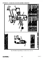
Page 35: ...Figure B3 bottom Figure B4 top 300 380 BX Actuator Assembly 34 4 04 Rev S ...
Page 36: ...Figure B5 300 380 BX Actuator Assembly 35 4 04 Rev S ...
Page 37: ...Figure B6 300 380 BX Actuator Assembly 36 4 04 Rev S ...
Page 38: ...Figure B7 bottom Figure B8 top 300 380 BX Actuator Assembly 37 4 04 Rev S ...
Page 39: ...Figure B9 bottom Figure B10 top 300 380 BX Actuator Assembly 38 4 04 Rev S ...
Page 40: ...Figure B11 bottom Figure B12 top 300 380 BX Actuator Assembly 39 4 04 Rev S ...
Page 41: ...40 Figure B13 300 380 BX Actuator Assembly 4 04 Rev S ...
Page 42: ...Figure B14 300 380 BX Actuator Assembly 41 4 04 Rev S ...
Page 44: ...Figure C3 Standard Handle Assembly 43 4 04 Rev S ...
Page 45: ...Figure C4 Standard Handle Assembly 44 4 04 Rev S ...
Page 46: ...Figure C5 bottom Figure C6 top Standard Handle Assembly 45 4 04 Rev S ...
Page 47: ...Figure C7 bottom Figure C8 top Standard Handle Assembly 46 4 04 Rev S ...
Page 48: ...Figure C9 bottom Figure C10 top Standard Handle Assembly 47 4 04 Rev S ...
Page 49: ...Figure C11 bottom Figure C12 top Standard Handle Assembly 48 4 04 Rev S ...
Page 50: ...Figure C13 Standard Handle Assembly 49 4 04 Rev S ...
Page 52: ...Figure D3 bottom Figure D4 top Float Mode Handle Assembly 51 4 04 Rev S ...
Page 53: ...Figure D5 bottom Figure D6 top Float Mode Handle Assembly 52 4 04 Rev S ...
Page 54: ...Figure D7 bottom Figure D8 top Float Mode Handle Assembly 53 4 04 Rev S ...
Page 55: ...Figure D9 bottom Figure D10 top Float Mode Handle Assembly 54 4 04 Rev S ...
Page 56: ...Figure D11 Float Mode Handle Assembly 55 4 04 Rev S ...
Page 58: ...Figure E2 Air Coil Cord Assembly Standard Float Mode 57 4 04 Rev S ...
Page 59: ...Figure E3 Remote Mount Coil Cord Standard Float Mode 58 4 04 Rev S ...
Page 60: ...Figure E4 Air Remote Mount Coil Cord Standard Float Mode 59 4 04 Rev S ...
Page 61: ...APPENDIX F CONTROLS SCHEMATIC DRAWINGS Figure F1 Remote Load Cell Assembly 60 4 04 Rev S ...
Page 62: ...Figure F2 BX Controls Schematic 61 4 04 Rev S ...
Page 64: ...Figure G2 BX G Force 300 380 Overall Dimensions 63 4 04 Rev S ...
Page 67: ...Figure I2 300 380 Standard Inline Component Layout 66 4 04 Rev S ...
Page 68: ...Figure I3 Standard Remote Mount Component Layout 67 4 04 Rev S ...


