4
G-Force® Operational Guidelines
All operators should read the G-Force® Instruction, Installation and Maintenance Manuals before
operating the unit. Please follow the instructions contained in these manuals for your safety and
for optimum trouble-free operation of your G-Force®. When repairing or maintaining a
G-Force®, use only Gorbel® recommended parts and materials.
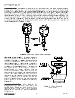
Read & follow all instruction
& warning information on or
attached to the G-Force
®
.
Check Wire Rope for
improper seating, twisting,
kinking, wear or defects
before operating.
Center G-Force
®
over the
load before lifting a load.
Do not end or side load.
Avoid swinging of load or
load hook when traveling
with the G-Force
®
.
Check the coil cord for
improper seating, twisting,
kinking, wear or defects
before operating.
Do not over-twist coil cable
assembly (>360°).
Damage and/or failure
could occur.
The Operator Present
switch should be depressed
the entire time the
G-Force
®
is in use.
Press Float Mode Button with
only the load weight hanging
from unit. Applying other
force will cause unit to drift.
The wire rope should never
be more than 20° out of
vertical while the
G-Force
®
is in use.
Do not bang the G-Force
®
into end stops repeatedly
or at a speed faster than a
normal walking pace.
G-Force®
Installation
&
Maintenance
Manual
1
10
9
8
7
6
5
2
Questions about G-Force
®
?
Call Gorbel
®
Customer
Service at (800) 821-0086 or
your local Gorbel
®
distributor.
?
12
Maximum Trolley Saddle for
the G-Force
®
is 12'.
See drawing for Trolley
Saddle definitions by unit size.
Maximum
Trolley
Saddle is
12'.
What is Trolley
Saddle?
150# unit:
The distance
from bottom of
wheels to floor.
300/380# unit:
The distance
from hoist trolley
clevis pin to the
floor.
11
4
3
4/04-Rev. S
®
Summary of Contents for 150 BX G-Force
Page 26: ...Figure A3 bottom Figure A4 top 150 BX Actuator Assembly 25 4 04 Rev S ...
Page 27: ...Figure A5 150 BX Actuator Assembly 26 4 04 Rev S ...
Page 28: ...Figure A6 150 BX Actuator Assembly 27 4 04 Rev S ...
Page 29: ...Figure A7 bottom Figure A8 top 150 BX Actuator Assembly 28 4 04 Rev S ...
Page 30: ...Figure A9 bottom Figure A10 top 150 BX Actuator Assembly 29 4 04 Rev S ...
Page 31: ...Figure A11 bottom Figure A12 top 150 BX Actuator Assembly 30 4 04 Rev S ...
Page 32: ...Figure A13 150 BX Actuator Assembly 31 4 04 Rev S ...
Page 33: ...Figure A14 150 BX Actuator Assembly 32 4 04 Rev S ...
Page 35: ...Figure B3 bottom Figure B4 top 300 380 BX Actuator Assembly 34 4 04 Rev S ...
Page 36: ...Figure B5 300 380 BX Actuator Assembly 35 4 04 Rev S ...
Page 37: ...Figure B6 300 380 BX Actuator Assembly 36 4 04 Rev S ...
Page 38: ...Figure B7 bottom Figure B8 top 300 380 BX Actuator Assembly 37 4 04 Rev S ...
Page 39: ...Figure B9 bottom Figure B10 top 300 380 BX Actuator Assembly 38 4 04 Rev S ...
Page 40: ...Figure B11 bottom Figure B12 top 300 380 BX Actuator Assembly 39 4 04 Rev S ...
Page 41: ...40 Figure B13 300 380 BX Actuator Assembly 4 04 Rev S ...
Page 42: ...Figure B14 300 380 BX Actuator Assembly 41 4 04 Rev S ...
Page 44: ...Figure C3 Standard Handle Assembly 43 4 04 Rev S ...
Page 45: ...Figure C4 Standard Handle Assembly 44 4 04 Rev S ...
Page 46: ...Figure C5 bottom Figure C6 top Standard Handle Assembly 45 4 04 Rev S ...
Page 47: ...Figure C7 bottom Figure C8 top Standard Handle Assembly 46 4 04 Rev S ...
Page 48: ...Figure C9 bottom Figure C10 top Standard Handle Assembly 47 4 04 Rev S ...
Page 49: ...Figure C11 bottom Figure C12 top Standard Handle Assembly 48 4 04 Rev S ...
Page 50: ...Figure C13 Standard Handle Assembly 49 4 04 Rev S ...
Page 52: ...Figure D3 bottom Figure D4 top Float Mode Handle Assembly 51 4 04 Rev S ...
Page 53: ...Figure D5 bottom Figure D6 top Float Mode Handle Assembly 52 4 04 Rev S ...
Page 54: ...Figure D7 bottom Figure D8 top Float Mode Handle Assembly 53 4 04 Rev S ...
Page 55: ...Figure D9 bottom Figure D10 top Float Mode Handle Assembly 54 4 04 Rev S ...
Page 56: ...Figure D11 Float Mode Handle Assembly 55 4 04 Rev S ...
Page 58: ...Figure E2 Air Coil Cord Assembly Standard Float Mode 57 4 04 Rev S ...
Page 59: ...Figure E3 Remote Mount Coil Cord Standard Float Mode 58 4 04 Rev S ...
Page 60: ...Figure E4 Air Remote Mount Coil Cord Standard Float Mode 59 4 04 Rev S ...
Page 61: ...APPENDIX F CONTROLS SCHEMATIC DRAWINGS Figure F1 Remote Load Cell Assembly 60 4 04 Rev S ...
Page 62: ...Figure F2 BX Controls Schematic 61 4 04 Rev S ...
Page 64: ...Figure G2 BX G Force 300 380 Overall Dimensions 63 4 04 Rev S ...
Page 67: ...Figure I2 300 380 Standard Inline Component Layout 66 4 04 Rev S ...
Page 68: ...Figure I3 Standard Remote Mount Component Layout 67 4 04 Rev S ...


