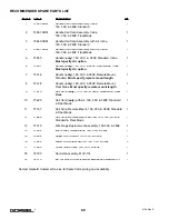
RECOMMENDED SPARE PARTS LIST
Item #
Part #
Description
Qty
1
73050.ASM
Handle-Coil Cord Assembly, Inline,
150, 300, & 380#, Standard
1
2
73051.ASM
Handle-Coil Cord Assembly, Inline,
150, 300, & 380#, Float Mode
1
3
73650.ASM
Handle-Coil Cord Assembly with Air, Inline,
150, 300, & 380#, Standard
1
4
73651.ASM
Handle-Coil Cord Assembly with Air, Inline,
150, 300, & 380#, Float Mode
1
5
73050
Handle (
only
), 150, 300, & 380#, Standard, Inline,
Must specify Air option
1
6
73051
Handle (
only
), 150, 300, & 380#, Float Mode, Inline,
Must specify Air option
1
7
73146
Handle (
only
), 150, 300, & 380#, Remote Mount,
Standard,
Must specify remote mount length
1
8
73148
Handle (
only
), 150, 300, & 380#, Remote Mount,
Float Mode,
Must specify remote mount length
1
9
77610
Coil Cord (
only
), 150, 300, & 380#, Standard & Float
Mode
1
10
77620
Coil Cord (
only
) with Air, 150, 300, & 380#, Standard
& Float Mode
1
11
77157
Coil Cord, Remote Mount, 150, 300, & 380#, Standard
& Float Mode
1
12
77665
Coil Cord, Remote Mount with Air, 150, 300, & 380#,
Standard & Float Mode
1
13
77315
Wire Rope Replacement Assembly, 150,300, & 380#
1
14
73099
Idler Pulley Guide Block, 150, 300, & 380#
1
15
75354
Upper Limit Switch, 150, 300, & 380#
1
16
77084
Lower Limit/Slack Switch, 150, 300, & 380#
3
17
77559
Offset Idler Pulley, 150, 300, & 380#
1
18
72190
Controls Assembly, MLD-114
1
19
78010
BX G-Force® Universal Miscellaneous Hardware Kit
1
Contact Gorbel® Customer Service for Spare Parts pricing and availability.
69
4/04-Rev. S
®
Summary of Contents for 150 BX G-Force
Page 26: ...Figure A3 bottom Figure A4 top 150 BX Actuator Assembly 25 4 04 Rev S ...
Page 27: ...Figure A5 150 BX Actuator Assembly 26 4 04 Rev S ...
Page 28: ...Figure A6 150 BX Actuator Assembly 27 4 04 Rev S ...
Page 29: ...Figure A7 bottom Figure A8 top 150 BX Actuator Assembly 28 4 04 Rev S ...
Page 30: ...Figure A9 bottom Figure A10 top 150 BX Actuator Assembly 29 4 04 Rev S ...
Page 31: ...Figure A11 bottom Figure A12 top 150 BX Actuator Assembly 30 4 04 Rev S ...
Page 32: ...Figure A13 150 BX Actuator Assembly 31 4 04 Rev S ...
Page 33: ...Figure A14 150 BX Actuator Assembly 32 4 04 Rev S ...
Page 35: ...Figure B3 bottom Figure B4 top 300 380 BX Actuator Assembly 34 4 04 Rev S ...
Page 36: ...Figure B5 300 380 BX Actuator Assembly 35 4 04 Rev S ...
Page 37: ...Figure B6 300 380 BX Actuator Assembly 36 4 04 Rev S ...
Page 38: ...Figure B7 bottom Figure B8 top 300 380 BX Actuator Assembly 37 4 04 Rev S ...
Page 39: ...Figure B9 bottom Figure B10 top 300 380 BX Actuator Assembly 38 4 04 Rev S ...
Page 40: ...Figure B11 bottom Figure B12 top 300 380 BX Actuator Assembly 39 4 04 Rev S ...
Page 41: ...40 Figure B13 300 380 BX Actuator Assembly 4 04 Rev S ...
Page 42: ...Figure B14 300 380 BX Actuator Assembly 41 4 04 Rev S ...
Page 44: ...Figure C3 Standard Handle Assembly 43 4 04 Rev S ...
Page 45: ...Figure C4 Standard Handle Assembly 44 4 04 Rev S ...
Page 46: ...Figure C5 bottom Figure C6 top Standard Handle Assembly 45 4 04 Rev S ...
Page 47: ...Figure C7 bottom Figure C8 top Standard Handle Assembly 46 4 04 Rev S ...
Page 48: ...Figure C9 bottom Figure C10 top Standard Handle Assembly 47 4 04 Rev S ...
Page 49: ...Figure C11 bottom Figure C12 top Standard Handle Assembly 48 4 04 Rev S ...
Page 50: ...Figure C13 Standard Handle Assembly 49 4 04 Rev S ...
Page 52: ...Figure D3 bottom Figure D4 top Float Mode Handle Assembly 51 4 04 Rev S ...
Page 53: ...Figure D5 bottom Figure D6 top Float Mode Handle Assembly 52 4 04 Rev S ...
Page 54: ...Figure D7 bottom Figure D8 top Float Mode Handle Assembly 53 4 04 Rev S ...
Page 55: ...Figure D9 bottom Figure D10 top Float Mode Handle Assembly 54 4 04 Rev S ...
Page 56: ...Figure D11 Float Mode Handle Assembly 55 4 04 Rev S ...
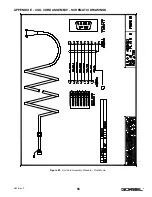
Page 58: ...Figure E2 Air Coil Cord Assembly Standard Float Mode 57 4 04 Rev S ...
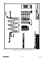
Page 59: ...Figure E3 Remote Mount Coil Cord Standard Float Mode 58 4 04 Rev S ...
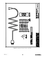
Page 60: ...Figure E4 Air Remote Mount Coil Cord Standard Float Mode 59 4 04 Rev S ...
Page 61: ...APPENDIX F CONTROLS SCHEMATIC DRAWINGS Figure F1 Remote Load Cell Assembly 60 4 04 Rev S ...
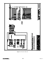
Page 62: ...Figure F2 BX Controls Schematic 61 4 04 Rev S ...
Page 64: ...Figure G2 BX G Force 300 380 Overall Dimensions 63 4 04 Rev S ...
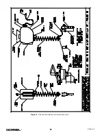
Page 67: ...Figure I2 300 380 Standard Inline Component Layout 66 4 04 Rev S ...
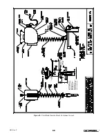
Page 68: ...Figure I3 Standard Remote Mount Component Layout 67 4 04 Rev S ...

