INSPECTION AND MAINTENANCE SCHEDULE
* Federal, state and local codes may require inspection and maintenance checks more often. Please check the
federal, state and local code manuals in your area.
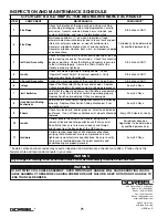
G-FORCE® BX ILD INSPECTION AND MAINTENANCE SCHEDULE
ITEM
COMPONENT
MAINTENANCE
FREQUENCY*
1
Wire Rope
Check for distortion of the rope such as kinking, crushing,
unstranding, birdcaging, main strand displacement, or core
protrusion. General corrosion, broken or cut strands, and
number, distribution, and type of visible broken wires
Start of each Shift
2
Wire Rope
Maintenance listed in (1), as well as reduction of rope
diameter below nominal diameter due to loss of core support,
internal or external corrosion, or wear of outside wires.
Severely corroded or broken wires at end connections.
Severely corroded, cracked, bent, worn, or improperly applied
end connections.
Periodically (to be determined
by qualified persons only)
3
Coil Cord Assembly
Check to make sure there is no excessive wearing of the coil
cable sleeving caused by the wire rope. Check for excessive
bends or pinching. Check that Mating Connector is secured
to the Actuator properly. Assure the Strain Relief at the
Handle is properly tightened.
Start of each Shift
4
Handle
Check for smooth operation of sliding handle. Check
“Operator Present Switch” for correct operation. Verify
proper handle Swivel functionality.
Start of each Shift
5
G-Force® Assembly
Conduct a visual inspection of the entire BX G-Force® unit.
Start of each Shift
6
Pulleys
Inspect the Slack-Idler Pulley for excessive wear. Replace
Pulleys immediately if excessive wear or damage is present.
Every 90 Days
7
Limit Switches
Verify that the Upper and Lower Limit Switches are operating
properly. Verify that the Slack Switch is operating properly.
Replace Switches immediately if they are damaged.
Every 90 Days
8
Slack Switch Sliding
Mechanism
Verify that the Slack Switch Sliding Mechanism is functioning
properly. Replace Slack Switch Sliding Mechanism if not
operating correctly.
Every 90 Days
9
Wheels
Check for cracks, pits, and/or grooves. All of these increase
pull forces. If any of these conditions exist, wheels should be
replaced.
Every 2000 Hours or Yearly
10
Handle
Perform general cleaning of the Handle, being sure to
remove all debris and foreign substances that may exist.
Specifically, take care to remove all debris and foreign
substances from the back side of the OPS Lever.
Periodically based on
Application (to be determined
by qualified persons only)
11
Hardware
Perform routine inspection of all hardware connections,
verifying that all lockwashers are compressed and nuts
tightened to manufacturer’s specifications. Be sure to verify
the jam nuts located between the swivel assembly and
handle/tooling are properly torqued.
Every 90 Days
WARNING
Any changes in rotating effort or unusual noises must be immediately identified and corrected.
WARNING
DO NOT TWIST COIL CABLE ASSEMBLY. OVER TWISTING OF HANDLE WILL CAUSE SHORTING IN COIL
CABLE ASSEMBLY, THEREFORE CAUSING PREMATURE UNIT FAILURE. KEEP ROTATION OF HANDLE TO
LESS THAN 360 DEGREES.
600 Fishers Run, P.O. Box 593
Fishers, NY 14453-0593
Phone: (800) 821-0086
Fax: (800) 828-1808
E-Mail: info@gorbel.com
http://www,gorbel.com
© 2004 Gorbel Inc.
All Rights Reserved
71
4/04-Rev. S
®
®
Summary of Contents for 150 BX G-Force
Page 26: ...Figure A3 bottom Figure A4 top 150 BX Actuator Assembly 25 4 04 Rev S ...
Page 27: ...Figure A5 150 BX Actuator Assembly 26 4 04 Rev S ...
Page 28: ...Figure A6 150 BX Actuator Assembly 27 4 04 Rev S ...
Page 29: ...Figure A7 bottom Figure A8 top 150 BX Actuator Assembly 28 4 04 Rev S ...
Page 30: ...Figure A9 bottom Figure A10 top 150 BX Actuator Assembly 29 4 04 Rev S ...
Page 31: ...Figure A11 bottom Figure A12 top 150 BX Actuator Assembly 30 4 04 Rev S ...
Page 32: ...Figure A13 150 BX Actuator Assembly 31 4 04 Rev S ...
Page 33: ...Figure A14 150 BX Actuator Assembly 32 4 04 Rev S ...
Page 35: ...Figure B3 bottom Figure B4 top 300 380 BX Actuator Assembly 34 4 04 Rev S ...
Page 36: ...Figure B5 300 380 BX Actuator Assembly 35 4 04 Rev S ...
Page 37: ...Figure B6 300 380 BX Actuator Assembly 36 4 04 Rev S ...
Page 38: ...Figure B7 bottom Figure B8 top 300 380 BX Actuator Assembly 37 4 04 Rev S ...
Page 39: ...Figure B9 bottom Figure B10 top 300 380 BX Actuator Assembly 38 4 04 Rev S ...
Page 40: ...Figure B11 bottom Figure B12 top 300 380 BX Actuator Assembly 39 4 04 Rev S ...
Page 41: ...40 Figure B13 300 380 BX Actuator Assembly 4 04 Rev S ...
Page 42: ...Figure B14 300 380 BX Actuator Assembly 41 4 04 Rev S ...
Page 44: ...Figure C3 Standard Handle Assembly 43 4 04 Rev S ...
Page 45: ...Figure C4 Standard Handle Assembly 44 4 04 Rev S ...
Page 46: ...Figure C5 bottom Figure C6 top Standard Handle Assembly 45 4 04 Rev S ...
Page 47: ...Figure C7 bottom Figure C8 top Standard Handle Assembly 46 4 04 Rev S ...
Page 48: ...Figure C9 bottom Figure C10 top Standard Handle Assembly 47 4 04 Rev S ...
Page 49: ...Figure C11 bottom Figure C12 top Standard Handle Assembly 48 4 04 Rev S ...
Page 50: ...Figure C13 Standard Handle Assembly 49 4 04 Rev S ...
Page 52: ...Figure D3 bottom Figure D4 top Float Mode Handle Assembly 51 4 04 Rev S ...
Page 53: ...Figure D5 bottom Figure D6 top Float Mode Handle Assembly 52 4 04 Rev S ...
Page 54: ...Figure D7 bottom Figure D8 top Float Mode Handle Assembly 53 4 04 Rev S ...
Page 55: ...Figure D9 bottom Figure D10 top Float Mode Handle Assembly 54 4 04 Rev S ...
Page 56: ...Figure D11 Float Mode Handle Assembly 55 4 04 Rev S ...
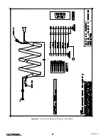
Page 58: ...Figure E2 Air Coil Cord Assembly Standard Float Mode 57 4 04 Rev S ...
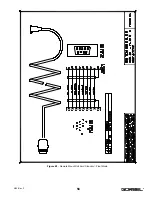
Page 59: ...Figure E3 Remote Mount Coil Cord Standard Float Mode 58 4 04 Rev S ...
Page 60: ...Figure E4 Air Remote Mount Coil Cord Standard Float Mode 59 4 04 Rev S ...
Page 61: ...APPENDIX F CONTROLS SCHEMATIC DRAWINGS Figure F1 Remote Load Cell Assembly 60 4 04 Rev S ...
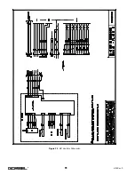
Page 62: ...Figure F2 BX Controls Schematic 61 4 04 Rev S ...
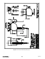
Page 64: ...Figure G2 BX G Force 300 380 Overall Dimensions 63 4 04 Rev S ...
Page 67: ...Figure I2 300 380 Standard Inline Component Layout 66 4 04 Rev S ...
Page 68: ...Figure I3 Standard Remote Mount Component Layout 67 4 04 Rev S ...

