STEP 3 - CASTER TO BASE CHANNEL CONNECTIONS
3.1
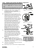
Assemble the appropriate hardware so that the heads of
the sixteen 1-1/2” long hex head bolts are located on the
top surface of the base channel (as shown in
Diagram 3A
).
3.2 For 1, 2 and 5 Ton Gantry Cranes utilizing optional
4-Position Swivel Locks only:
The optional 4-Position
Swivel Locks (4PSL) are installed via a bolted connection
(unlike the 3 Ton Gantry Cranes which accept a 4PSL
that is pre-welded to the caster). Ensure that the 4PSL’s
are installed on the under-side of the caster base plate.
To install the 4PSL’s align the two slotted holes in the swivel
lock with two slotted holes (either holes 1 & 2 only or holes
3 & 4 only) on the short side of the caster base plate (as
shown in
Diagram 3B
).
3.3
Tighten caster hardware (refer to
Chart 2A
, on page 3, for proper torque rating).
3.4
You are now ready to erect the assembled Gantry Crane into the upright position. Ensure
that the hitch pin assemblies are still properly engaged in upper and lower vertical tube
holes and that the safety hair pins are intact.
Carefully and safely
(by means of rigging
(straps/slings are preferred to reduce paint damage) that is sized and oriented correctly for
raising the load) lift and rotate the Gantry Crane onto its casters by means of an overhead
lifting device or lift truck. Use Gorbel® Blue touch-up paint (provided) to cover any
scratches and abrasions as needed.
3.5
If your Gantry Crane is equipped with the optional cam brakes (pre-installed prior to
receiving them) you may use your hand or foot to engage the brake for each caster by
pressing down on one of the cam brake foot pedals located on the sides of the casters.
Try moving the Gantry Crane after engaging the cam brakes to ensure that they are
properly engaged.
3.6 For Gantry Cranes utilizing optional Steel V-Groove Casters only:
Install the
assembled Gantry Crane onto the V-Track per the manufacturer’s instructions.
TIP:
To install casters, assemble while the Gantry Crane is
still lying on its side (as shown in
Diagram 2A
on pg. 3).
TIP:
Choose the 2 outer-most slotted holes when
mounting the 4PSL. This will ensure that the 4PSL pull
ring will be accessible from the outside of the formed
base channel allowing you to engage or disengage the
spring loaded pin from the locking caster slots. If the
4PSL is pre-welded to the caster simply rotate the caster
assembly so that the 4PSL faces outward.
Diagram 3A.
Caster Assembly.
Diagram 3B.
Caster Base Plate.
WARNING
Ensure that NO ONE is standing near or in the vicinity of the crane while it is being erected.
WARNING
Ensure there are no other obstructions that might hinder the crane from being erected.
4
9/19


