background image

STEP 3 - PIVOT PRO® (FREE STANDING) MAST INSTALLATION

3.1  INSTALLING ANCHOR BOLTS


3.1.1  Square Base Plates 

  (4-bolt 

pattern):


A)  Anchor bolts (by others) for


     base plates must:


     •  be 3/4” in diameter.


     •  be embedded at least 4” into


floor, not to exceed 3/4 of floor

  depth 

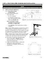
(see 

diagram 3A

).


Note:

  A minimum 6” thick


reinforced concrete floor is

  required 

(

see


diagram 3B

).


     •  have 

minimum

 of two threads above nut after   

  installation
 

Note:

  PIVOT PRO® foundation requirements are based  


on soil pressure of 2500# per square foot. Concrete 


pressure recommended for jib crane foundation is 3000#  


per square inch of compressive force, with no cracks or  


seams in a 48” square area around center of mast.


Note:

  Chemical (epoxy) anchor bolts are recommended  


because of their ability to withstand the vibrating loads  


caused by the rapid raising or lowering of the load.


B)  Drill holes in concrete floor using pre-drilled


     holes in base plate or 

diagram 3C

 as a


     guide (use drill bit size recommended by


     anchor bolt manufacturer).


C)  Install anchor bolts (Grade 5 or better) and


     hardware (by others) according to


     manufacturer’s installation directions and


     requirements.


STOP!

Do not proceed if your support structure does not meet the loading requirements determined in 

Step 1.4

.

Diagram 3A. 

 Typical square base plate anchor bolt embed

ment.

Diagram 3C. 

 Square base plate pattern.

8

9/18

Diagram 3B. 

 Foundation Requirements.

CONCRETE IS 

NORMAL WEIGHT, 

STONE AGGREGATE

6”

48” SQ.

Summary of Contents for Free Standing PIVOT PRO

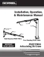
Page 1: ...ANT DO NOT DESTROY Installation Operation Maintenance Manual Month Year Gorbel Dealer Date PIVOT PRO Articulating Jib Crane Gorbel Customer Order No Serial No Wall Mounted PIVOT PRO Free Standing PIVO...

Page 2: ...lation 6 7 Step 3 PIVOT PRO Free Standing Mast Installation 8 9 Step 4 PIVOT PRO Free Standing Boom Installation 10 11 Step 5 Vacuum Hose Installation 12 Step 6 Accessories Optional Installation 13 15...

Page 3: ...standard fabrication practices should be employed to assemble these cranes because of the necessity of properly interpreting these instructions Gorbel is not responsible for the quality of work mansh...

Page 4: ...ve action taken Operating Suggestions One measure of a good crane operator is the smoothness of the crane operation The good crane operator should know and follow these proven suggestions for safe eff...

Page 5: ...well as time and money DON TS HOISTS VACUUM LIFTERS 1 Never lift or transport a load until all personnel are clear and do not transport the load over personnel 2 Do not allow any unqualified personne...

Page 6: ...hardware box General Arrangement Drawing can be found inserted in this installation manual WARNING Consult a qualified structural engineer to determine that your support structure is adequate to suppo...

Page 7: ...O FS 50 12 12 T PPRO FS 50 12 12 B 916 75 10 8 PPRO FS 75 10 8 T PPRO FS 75 10 8 B 668 10 PPRO FS 75 10 10 T PPRO FS 75 10 10 B 897 12 PPRO FS 75 10 12 T PPRO FS 75 10 12 B 1142 12 8 PPRO FS 75 12 8 T...

Page 8: ...re 2 5 Clean pivot pins with clean dry cloth Slide bearings on pivot pins Be sure to orient bearings correctly diagram 2C 2 6 Lift boom weldment up and insert lower pivot pin into lower pivot mounting...

Page 9: ...nment 2 11 Attach two brake pads to the lower pivot mounting assembly using two 1 4 socket head cap screws lock washers and lock nuts diagram 2F 2 12 Adjust brake by tightening two lock nuts to achiev...

Page 10: ...acks or seams in a 48 square area around center of mast Note Chemical epoxy anchor bolts are recommended because of their ability to withstand the vibrating loads caused by the rapid raising or loweri...

Page 11: ...st plate approximately where cam followers will contact mast pipe distance between plumb line and face of mast should also be three 3 inches F Repeat steps D E every 60 around the mast to ensure that...

Page 12: ...in hole is slightly offset This collar may be installed in one of two ways flipped to act as a 0 025 thick shim When properly shimmed the holes on safety collar and pivot pin will be aligned Using ham...

Page 13: ...g for 45 adjustment increments Two rotation limits are supplied with the Free Standing PIVOT PRO A Swing boom to maximum rotation in one direction B Back off boom rotation until first available hole i...

Page 14: ...Install fittings into 2 NPT couplings of boom Do NOT over tighten PVC fittings should not be tightened more than 2 turns past finger tight 5 4 Place hose clamp over hose end push hose end over barbed...

Page 15: ...MUST BE supported by all four adjustable feet and NOT by the fork pockets Tighten jam top nut D Secure boom or assemble mast to base prior to boom assembly E Lower mast onto protruding bolts of base...

Page 16: ...ientation The filter bracket can be mounted vertically or horizontally depending on the filter s bolt hole locations A Transfer filter mounting pattern to the filter bracket B Drill filter bracket for...

Page 17: ...6 18 x 3 4 long hex head cap screw Tighten to 15 ft lbs C Position your lifter tube controls onto the smart hook 6 5 INSTALLING ROTATION STOPS ON WALL MOUNTED PIVOT PRO diagram 6E Contact Gorbel Custo...

Page 18: ...hers are compressed 7 2 If necessary touch up crane with paint provided 7 3 Keep Packing List Installation Manual General Arrangement Drawing and any other inserts filed together in a safe place TIP D...

Page 19: ...TOR NOT AN AGENT Gorbel and Purchaser agree that Purchaser has been put on notice that dealer or distributor is not Gorbel s agent in any respect for any reason Gorbel and Purchaser also agree that Pu...

Page 20: ...and square washer are properly installed so that boom cannot dislodge Every 2000 hours or yearly 5 Rotation Limits Check for deformation Make sure that bolt is tightened Replace block if deformed Eve...

Reviews: