11
9/18
STEP 5 - PIVOT PRO® (FREE STANDING) BOOM INSTALLATION (CONT.)
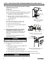
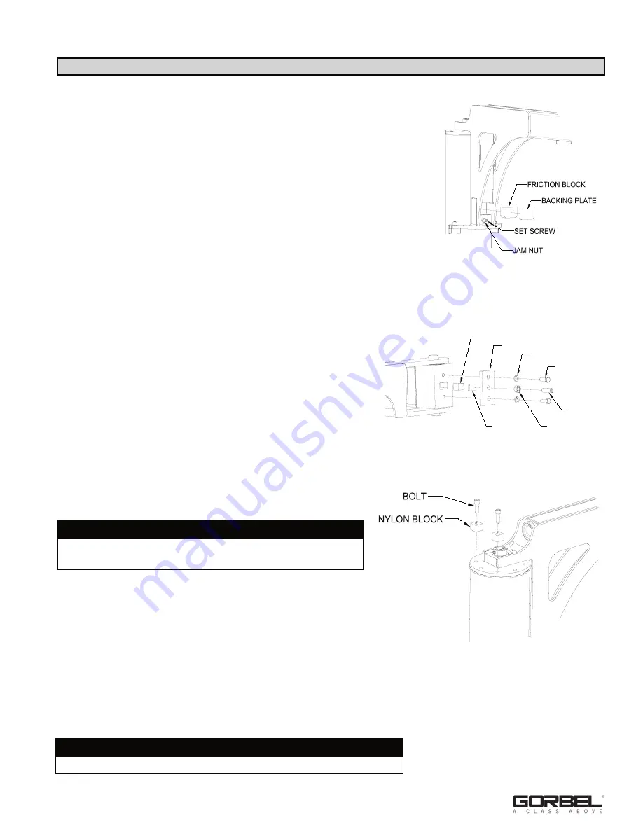
4.6 INSTALLING FRICTION BRAKES ON FREE STANDING
PIVOT PRO® (
diagram 4E
)
Primary Arm
A) Loosen set screw and jam nut.
B) Place friction block and backing plate between mast and
boom as shown. Bottom of block and plate should rest
squarely on top of cam follower plate.
C) Adjust set screw for desired rotational resistance.
DO NOT adjust such that cam followers are no longer
in contact with mast.
D) Tighten jam nut.
Secondary Arm Adjustment (
diagram 4F
)
E) Loosen set screw and jam nut.
F) Adjust set screw to desired rotational resistance
G) Tighten jam nut.
4.7 INSTALLING ROTATION STOPS ON FREE
STANDING PIVOT PRO® (
diagram 4G
)
Eight rotation limit holes are located on the top
plate of the mast allowing for 45° adjustment
increments.
Two rotation limits are supplied with the Free
Standing PIVOT PRO®.
A) Swing boom to maximum rotation in one
direction.
B) Back off boom rotation until first available hole
in top plate is exposed.
C) Install nylon block. Orient block such that
block diagonal is radial to pivot pin center.
D) Gently swing boom until boom sideplate is in full contact with nylon block.
E) Tighten block with 3/8” allen wrench until nylon material is slightly compressed.
Diagram 4E.
Installing friction
brakes on the Free Standing
PIVOT PRO®.
NYLON FRICTION PAD
BRAKE PLATE
ADJUSTMENT PLATE
LOCKWASHER
BOLT
SET SCREW
JAM NUT
Diagram 4F.
Adjusting the secondary arm
on the Free Standing PIVOT PRO®.
Diagram 4G.
Installing rotation stops on the
Free Standing PIVOT PRO®.
WARNING
Rotation Stops are meant to limit rotation, not stop rotation.
WARNING
At least one rotation stop must be installed to prevent
tangling and tugging of vacuum, air, or electric hoses.

