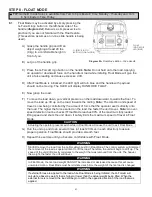
STEP 4 - COIL CORD INSTALLATION
Note:
G-Force® units, standard in-line or remote mounted, that are ordered from the
factory will be shipped with the coil cord assembled to the actuator wear ring and the
coil cord footer, creating the coil cord assembly (
diagrams 4A
and
4B
). In addition,
units ordered with air power will have a 1/4” ID nycoil air hose coil cord assembled
onto the coil cord assembly (not shown).
4.1
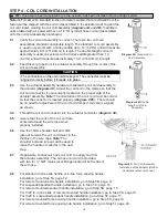
Verify the coil cord assembly is correct. There are two coil cord
assemblies: standard and double length. The standard coil cord assembly
is used on systems with a trolley saddle up to 14’ (4.27m) and will measure
approximately 8.3” (211.46mm) in length. The double length coil cord
assembly is used on systems with a trolley saddle greater than 14’
(4.27m) and will measure approximately 16.4” (415.93mm) in length.
4.2
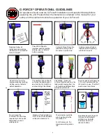
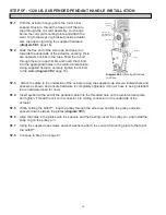
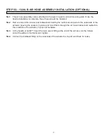
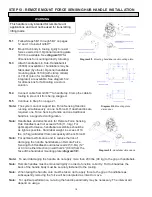
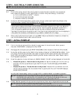
Feed the wire rope from the actuator assembly through the center of the
coil cord assembly.
4.3
Use the actuator assembly hardware to fasten the coil cord assembly to
the actuator (
diagram 4C
). Adjust the coil cord in the clamps so that the
coil cord connector is conveniently located on the proper side of the
actuator assembly.
Note:
The orientation of the coil cord must be correct
so that the connector is located properly (
diagram 4DC
). There should
be no need for adjustment of the coil cord clamps if coil cord is aligned
as shown.
4.4
Thread the coil cord connector into the actuator connector (
diagram 4C
).
4.5
Assure that the coils of the coil cord are
centered around the wire rope when
properly installed.
4.6
Use the 16mm shoulder bolt and M12
jam-nut to retain the coil cord footer to the
thimble in the wire rope.
Note:
The
shoulder bolt and jam-nut will be used to
retain the handle or collector in the next
step.
4.7
If applicable, connect air hose coil cord to supply line from
the actuator assembly. The air hose coil cord is provided
with two (2) ¼” NPT male swivel fittings located at both ends of
the air hose.
Diagram 4A.
Standard Coil
Cord Assembly.
Diagram 4B.
Double
Length Coil Cord
Assembly.
4.8
For standard in-line slide handle or in-line force sensing handle
installation, go to Step 5A, page 12.
For remote mounted slide handle installation, go to Step 5B, page 12.
For suspended pendant handle installation, go to Step 5C, page 14.
For remote mounted pendant handle installation, go to Step 5D, page 15.
For 1320 lb. in-line slide or remote mounted handle installation, go to Step 5E, page 16.
For 1320 lb. suspended pendant handle installation, go to Step 5F, page 17.
For remote mounted force sensing handle installation, go to Step 5H, page 19.
For remote mounted force sensing hub handle installation, go to Step 5I, page 20.
CAUTION
The connectors on the coil cord are keyed. The connector must be
aligned correctly before it threads into place.
TIP:
This step is best completed once the actuator has been installed into the bridge system.
Diagram 4C.
Coil Cord Assembly
Installation at the Actuator (Bottom
view/black center not shown).
10


