STEP 5H - REMOTE MOUNT FORCE SENSING SLIDE HANDLE INSTALLATION
5H.1
Follow Steps 5B.1 through 5B.7 on
pages 12 and 13 to install G360™.
5H.2
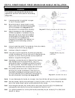
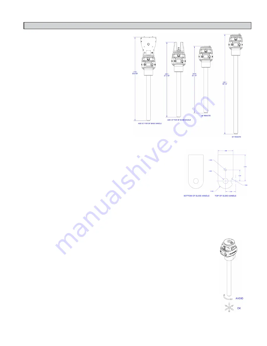
Bracket must be sized to fit the handle
it will be holding and rigid enough to
resist the forces exerted on it
(
diagram 5H1
).
5H.3
Using the included M16 hardware,
fasten both ends of the handle to the
bracket. Attach bracket to tooling if
necessary.
5H.4
Connect cable from G360™ to handle
top. Clamp the cable to tooling to
prevent it from being snagged.
5H.5
Continue to Step 6 on page 21.
Note:
The system cannot support two Force
Sensing Handles running simultaneously
on one G-Force®. If dual handles are
required, one Force Sensing Handle and
one traditional handle is a supported
configuration.
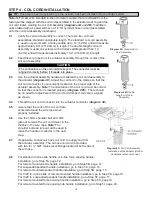
Diagram 5H1.
Force Sensing Slide Handle bracket sizes.
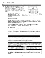
Note:
Due to the nature of the Force Sensing Slide Handle, excessive
twisting of the grip may be interpreted as intended motion. For best
results, only push and pull the handle grip while avoiding twisting
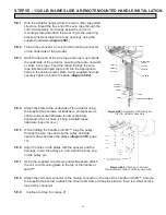
(
diagram 5H3
).
Note:
To avoid damaging the handle, do not apply more than 200 lbs (90 kg)
to the grip or handlebars.
Note:
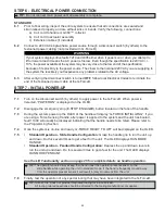
Remote handles must be mounted rigidly in order to function
correctly. For slide handles, the mounting holes on the tooling must be
aligned to avoid any binding of the handle and the bolts at each end of
the handle must be tightened enough to prevent motion but not induce
binding. The included rubber washers must be mounted between the
handle and tooling to prevent binding. Additionally, the handle must be
captured via the
.
Note:
Do not attach anything to the grip of the Slide Force Sensing Handle as
performance will be degraded.
Note:
Changing the orientation of the handle (tilting) while the system is live may be
interpreted as intent to move. It is recommended that the handle remains vertical
at all times during use.
Note:
When taring the handle, care must be taken not to apply force to the grip or
handlebars as subsequently removing the force will be interpreted as intent to
move.
Note:
For optimal performance, re-taring the handle periodically may be necessary.
The interval will depend on usage.
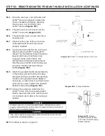
Diagram 5H2.
Remote handle
mounting dimensions
Diagram 5H3.
Proper use
of Force Sensing Handle
grip
18

