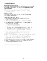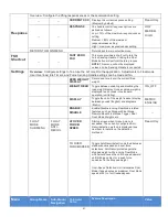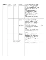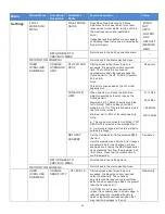
LIFT FUNCTIONALITY (CONTINUED)
Program Mode:
In this mode, the operator
can control speed, acceleration,
service features and other variable settings
(
diagram B
or
C
).
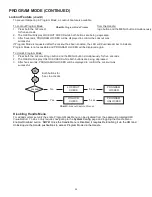
See the Program Mode
section, page 25, for complete programming
functionality located at the handle.
Float Mode LED (Blue):
The “Float Mode”
enabled LED will illuminate with the G-Force
logo button is pressed on the hand controller
and Float Mode has been correctly initiated.
This LED is located just above the G-Force®
MENU button (
diagrams B and C
).
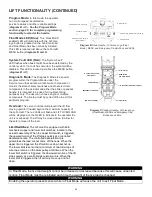
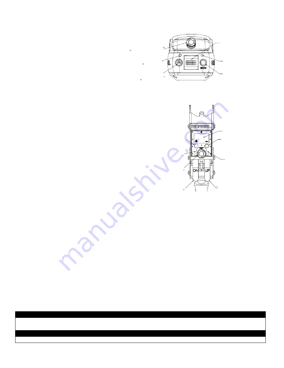
EMERGENCY STOP BUTTON
_
POTENTIOMETER
__
G-FORCE LOGO BUTTON
(FLOAT MODE)
_
OLED DISPLAY
MULTICOLOR INDICATOR LED (RGB)
MENU BUTTON
System Fault LED (Red):
The “System Fault”
LED flashes when basic faults have been detected by the
control system. If a fault has occurred, the system will be
disabled. This LED is located just above the MENU button
(
diagram B
or
C
).
Diagnostic Mode:
The Diagnostic Mode is a special
program within the Program Mode under the
Service menu that will allow a technician to measure or
monitor the state of select switches and other electronic
components in the actuator and either the slide or pendant
handle. It is intended to be used for troubleshooting
purposes only. The user can choose single or multiple
components. The E-stop must by cycled off/on to exit this
particular program.
Overload:
The servo controller will prevent the lift from
moving upward if loaded beyond the maximum capacity of
the G-Force®. The red LEDs will flash and LIFT OVERLOAD
will be displayed on the OLED to indicate to the operator the
unit is overloaded. The lift may be moved down to allow for
the safe removal of the load.
Limit Switches:
The G-Force® is equipped with both
mechanical upper and lower limit switches, located in the
actuator assembly. When the upper limit switch is triggered,
the upward motion of the lift stops quickly at a controlled
deceleration rate. The controlled deceleration rate
guarantees the load cannot come off the hook. When the
upper limit is triggered, the lift will move down but not up.
The lower limit is set so that a minimum of two full wraps of
wire rope remain on the drum pulley at all times. When the
lower limit switch is triggered, the downward motion of the lift
stops quickly at a controlled deceleration rate. When the
lower limit is triggered, the lift will only move up and not
down.
G-FORCE LOGO BUTTON
(FLOAT MODE)
POTENTIOMETER
EMERGENCY STOP BUTTON
DOWN LEVER (LOWER)
OLED DISPLAY
MENU BUTTON
(PROGRAM MODE)
MULTICOLOR INDICATOR LED (RGB)
WARNING
In Float Mode, the live load weight cannot be increased or decreased because this will cause unwanted
motion. Float Mode must be reinitiated each time the weight of the live load is changed.
WARNING
Enabling the operator present sensor while in Float Mode will cause the unit to exit Float Mode.
Diagram B.
Slide Handle - G-Force
®
Logo (Float
Mode), MENU and Emergency-Stop Buttons and LEDs.
Diagram C.
Pendant Handle - G-Force
®
Logo
(Float Mode), MENU and Emergency-Stop
Buttons and LEDs.
UP LEVER (RAISE)
25


