G-F
ORCE
®
MAIN ASSEMBLY COMPONENT DESCRIPTION
Prior to installing the G-Force® it is a good idea to familiarize yourself with the main components.
Standard Assembly:
The G-Force® consists of three (3) main assemblies and they are as
follows:
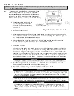
1)
Actuator (
diagram 1
):
The actuator assembly contains
the lifting power transmission of the G-Force®. The drive
assembly of the actuator consists of the servomotor with
failsafe brake, gearbox, main drum pulley, and controls.
The actuator assembly also contains the upper and lower
limit switches.
See the Lift Functionality section (page
25) and Controls Interface Features section (page
28) for additional details.
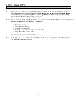
2)
Coil Cord Assembly (
diagram 2
):
The coil cord assembly
carries signals from the handle to the actuator assembly
which will include lift speed, lift direction and emergency
stop. Do not restrain coil cord to any foreign objects. Do
not hang or strain relief additional cable or festooning from
the
.
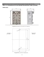
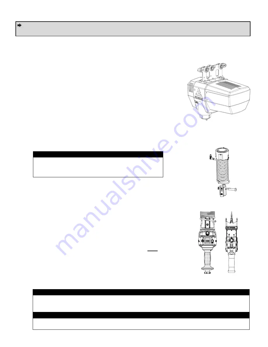
3)
Handle (
diagram 3
):
The handle is the main interface between the
operator and the lifting device.
See the Lift Functionality section
(page 25) and Controls Interface Features section (page 28) for
additional functionality located at the handle.
The Gorbel® slide
handle can accommodate either a Gorbel® load hook or tooling
(supplied by others). Tooling must meet the guidelines set forth by
Gorbel, Inc (
see Tooling Integration Guidelines on page 3
). Improper
tooling integration will result in degraded performance and premature
failure of the G-Force®.
The Q2 and iQ2 G-Force® Actuators are only compatible with Q2
and iQ2 Handles and vice-versa. This hardware is
NOT
backward
compatible with prior generation units.
*
Image depicts an inline Slide Handle. Certain applications may be
more appropriate for use with an inline Force Sensing Handle. Contact
your Gorbel® G-Force® Dealer for more information.
Diagram 2.
Standard Coil
Cord Assembly.
Diagram 3.
In-line Slide
Handle* and Pendant Handle.
WA
WARNING
The quick disconnects on the coil cord are keyed. The
connector must be aligned correctly before it threads into
place.
WARNING
The unique serial number for this unit can be found on the front cover of this manual, the bottom of
the actuator assembly, and the handle. Always have this serial number available during all
correspondence regarding your G-Force or when ordering repair parts.
WARNING
Do not field modify the G-Force in any way. Any modification, without the written consent of Gorbel
Inc, will void warranty.
TIP:
The G-Force® comes in 4 Capacities. The 2 largest capacities, 660 lbs. & 1320 lbs. (300kg &
600 kg) are identical in terms of Hardware and Software internal to the Actuator.
Diagram 1.
Actuator Assembly
8


