INSTALLATION
STEP 1 - UNPACKING THE G-FORCE
®
1.1
Carefully remove all items from the box.
1.2
Verify that all components listed on the packing slip are included.
1.3
If any items are missing or were damaged during shipping, please contact Gorbel® Inside
Sales or After the Sales Service (ATSS) immediately at (800) 821-0086 or (585) 924-
6262.
STEP 2 - PRE-ASSEMBLY / TOOLS REQUIRED
2.1
Read this entire Operator’s Manual
before
beginning installation of the G-Force®.
2.2
Tools and materials (by others) typically needed to install/assemble a G-Force® are as follows:
• 5mm Allen wrench
• 19mm hex socket
• 8mm Allen wrench
• Plastic cable tie straps
• 2.5mm Allen wrench
• Ladders/man lifts
• 6mm Allen wrench (1320 lb. only)
• 10mm wrench
• 14mm wrench or hex socket
• Snap ring pliers
• 3mm Allen wrench
STEP 3 - ACTUATOR ASSEMBLY INSTALLATION
3.1
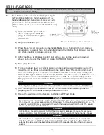
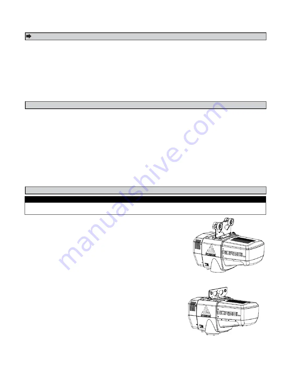
The standard G-Force® will come with the wheels
pre-assembled to the actuator trolley (
diagram 3A
).
When a Gorbel® G-Force® is to be used on a
non-Gorbel® bridge system, a universal adapter trolley is
required (
diagram 3B
).
Note:
The customer must provide
two (2) hoist trolleys when the unit will run in a
non-Gorbel® bridge system.
3.2
Ensure the power cord from the actuator is facing the
festooning side of the bridge/monorail. Remove the end
stop from the bridge and install the G-Force® actuator into
the track. Immediately reinstall the end stop. Verify that
the G-Force® trolley wheels are correct for the style and
capacity track that the unit is being installed on by rolling
the actuator assembly along the full length of the bridge to
ensure that the travel is smooth throughout.
Diagram 3A.
Standard Actuator Assembly.
Diagram 3B.
Standard Actuator Assembly
with Universal Adapter Trolley.
WARNING
DO NOT
lift the actuator by grabbing the blue plastic end covers. To lift the actuator, grab the handle
slots in the trolley.
TIP:
Packing list can be found in plastic pocket attached to shipping box.
9


