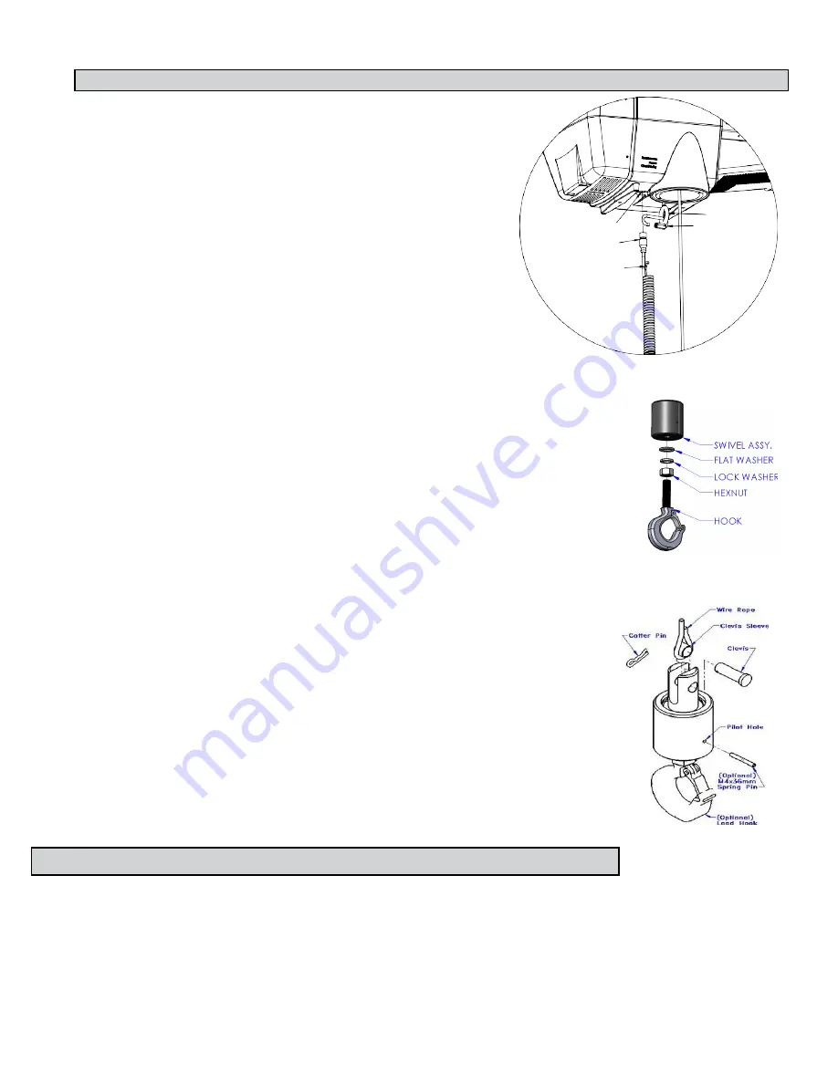
STEP 5C - SUSPENDED PENDANT HANDLE INSTALLATION
5C.1
Assure that the coils of the pendant handle coil cord are
centered around the pendant handle wire rope.
5C.2
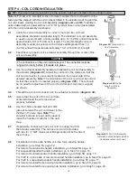
Remove the eyebolt from suspended pendant cable
assembly using the threaded connector.
5C.3
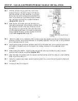
Thread the eyebolt into the bottom of the actuator
assembly as shown (
diagram 5C1
).
5C.4
Reattach the suspended pendant cable assembly to the
eyebolt via the threaded connector.
5C.5
Adjust the suspended pendant cable assembly so that
there is a service loop in the wiring cable and there is
no tension in the wire cable.
5C.6
Thread the cable assembly connector into the actuator
connector (
diagram 5C1
).
5C.7
Remove the cotter pin and clevis from the wire rope
swivel assembly.
Diagram 5C1.
Assembly of Suspended Pendant
Cable Assembly to Bottom of Actuator Assembly.
5C.8
Optional:
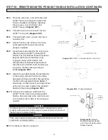
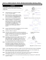
Install the hook or tooling with the washer, lock washer and nut
in the orientation shown (
diagram 5C2
) then use the pilot hole and a #21
drill bit to drill through the hook threads, a minimum of 36mm deep. Use a
hammer to insert the M4x36mm spring pin into the hole until it is flush
with the surface of the swivel assembly (
diagram 5C3
).
5C.9
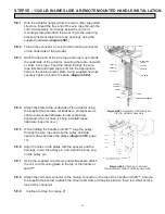
Reinsert the clevis and cotter pin capturing the wire rope thimble in the
swivel assembly (
diagram 5C3
).
5C.10
Continue to Step 6 on page 21.
Note:
On suspended pendant equipped systems, the wire rope swivel
assembly must be installed before AC power is applied to the system
or a limit switch error will occur (501 / 11000 error codes). To clear
this fault you will have to (must be done in this order):
1.
Install wire rope swivel assembly or other weighted device on
wire rope.
2.
Disconnect AC power from the system (using the e-stop will
not work).
3.
Reconnect the AC power and wait approximately one minute
for system to power on completely.
Diagram 5C2.
Hook
installation.
STEP 5D - REMOTE MOUNTED PENDANT HANDLE INSTALLATION
5D.1
Ensure the wire rope is still fed through the center of the coil cord. Hold the
G360 swivel just below the coil cord.
5D.2
Center the coil cord between the ears of the G360 swivel. Note: Make sure the fin of the coil cord footer
is on the opposite side of the G360 connector.
5D.3
Remove the 16mm shoulder bolt from the coil cord footer and wire rope and allow the coil cord footer and
wire rope to slide down into the G360™ swivel.
Actuator Connector
Eyebolt With Hexnut
Threaded Connector
Cable Assembly
Connector
Suspended Pendant
Cable Assembly
Diagram 5C3.
Cotter
Pin, Clevis, Wire Rope
Swivel Assembly, and
Wire Rope Thimble
13


