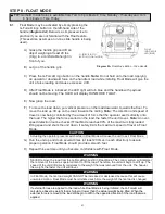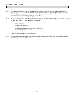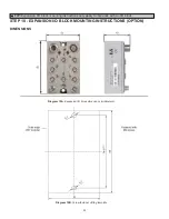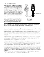
STEP 5D - REMOTE MOUNTED PENDANT HANDLE INSTALLATION (CONTINUED)
5D.4
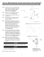
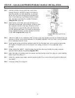
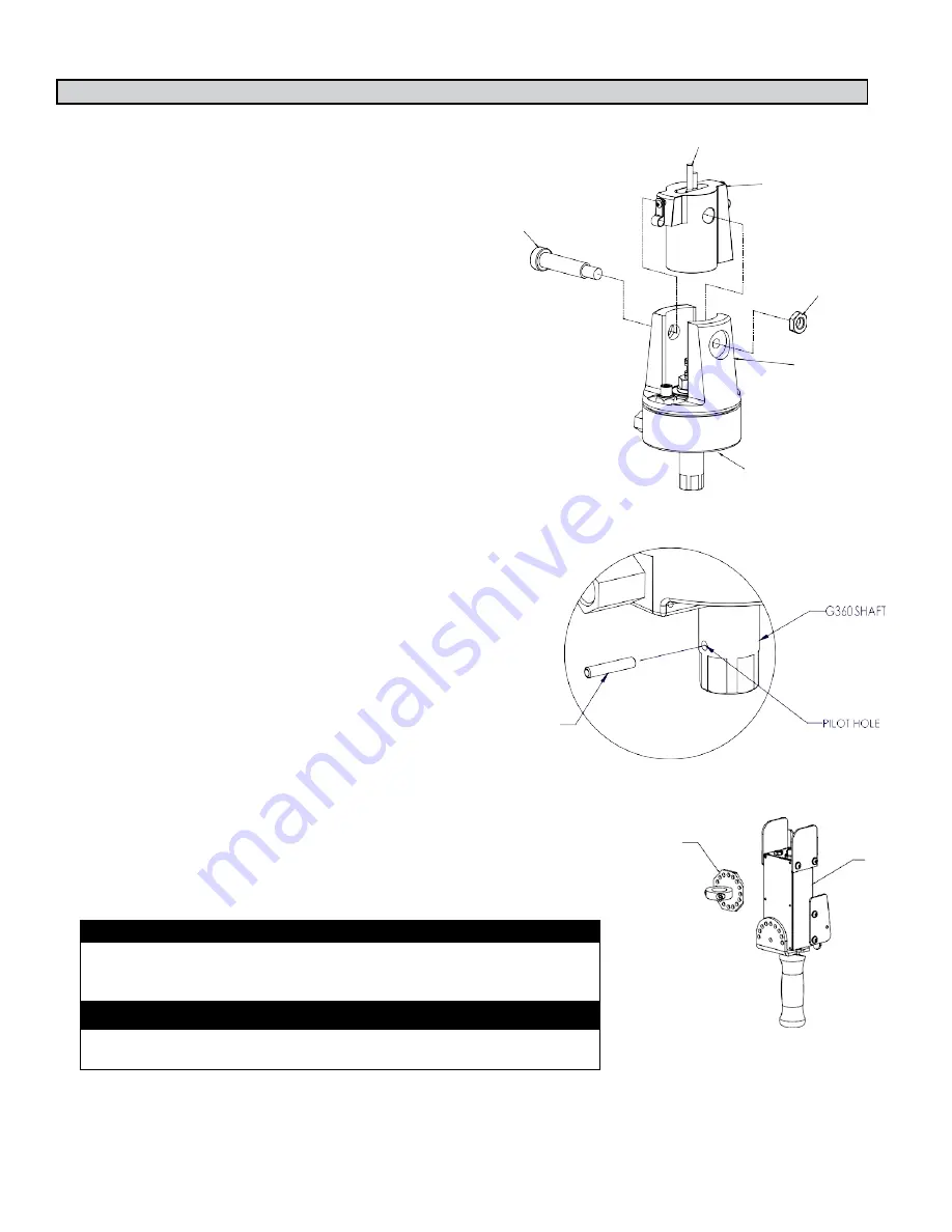
Once the wire rope, coil cord footer and
G360™ swivel are aligned, replace the
16mm shoulder bolt thereby capturing
the wire rope, coil cord footer and
G360™ swivel (
diagram 5D1
).
5D.5
Thread the coil cord connector into the
G360™ connector (
diagram 5D1
).
5D.6
Thread the M12 jam nut onto the 16mm
shoulder bolt.
5D.7
Check that the coils of the coil cord are
centered around the wire rope when
properly installed.
5D.8
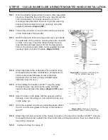
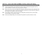
A pilot hole is provided for the locking pin.
Attach tooling to G360™ utilizing M16
thread. The tool bolt/rod thread should be
beyond pilot hole of shaft when fully
engaged. Using a #21 drill bit, drill
through the tool bolt/rod thread and out
the other side of G360 shaft. Hammer pin
into place, thereby locking tooling to
G360 (
diagram 5D2
).
16 mm Shoulder Bolt
**COIL CORD HAS BEEN
REMOVED FOR CLARITY
Wire Rope
Coil Cord Footer
M8 Jam Nut
G360 Swivel
STRAIN-RELIEF CLAMP - MUST BE
USED TO PREVENT DAMAGE TO G360
5D.9
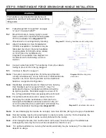
Attach the pendant handle bracket directly
to the tooling. Assure that the mounting
arrangement does not affect the operating
function of the pendant handle.
Note:
If
necessary, a collar clamp mounting bracket
option can be used to attach the pendant
handle to the tooling (
diagram 5D3
).
5D.10
Connect the extension cable from the
G360™ to the remote mounted pendant
handle. Securely clamp the remote mount
coil cord extension cable to the tooling as
needed.
5D.11
Continue to Step 6 on page 21.
CAUTION
All cables used in a remote mounted handle configuration must be
properly clamped and/or strain relieved to prevent premature failure of
the G-Force or customer tooling.
CAUTION
Take care to avoid looping excess cable at locations where the loop
could catch on foreign objects.
Diagram 5D1.
G360™, Shoulder Bolt and Coil Cord.
CLAMP COLLAR
REMOTE
MOUNTED
PENDANT
HANDLE
Diagram 5D3.
Remote
Mounted Pendant Handle
with Collar Clamp Mounting
Bracket (option)
Diagram 5D2.
Tooling Installation
14


