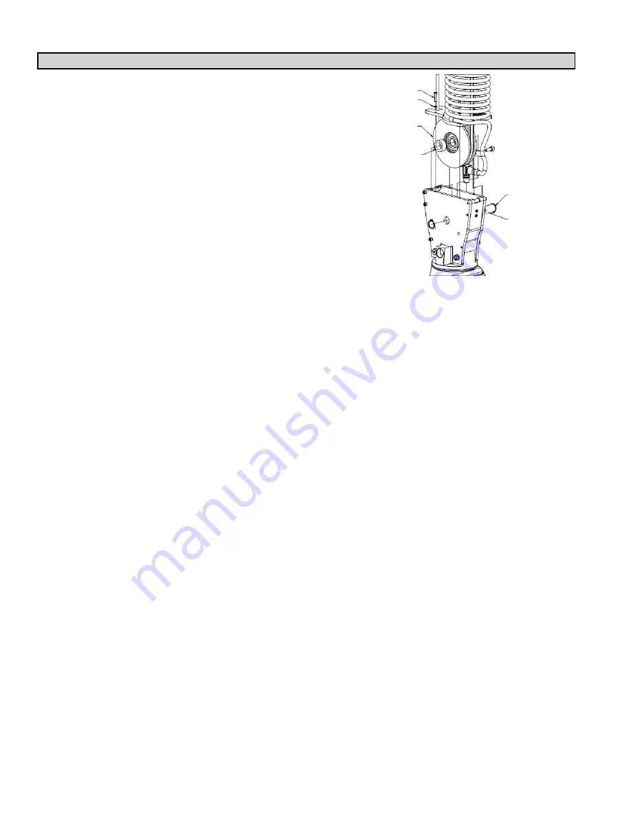
STEP 5F - 1320 LB. SUSPENDED PENDANT HANDLE INSTALLATION
5F.1
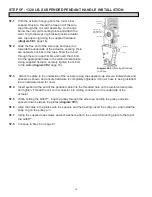
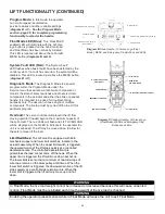
With the actuator hanging from the rail or other
support structure, thread the free end of the wire
rope through the coil cord assembly, so it hangs
below the coil cord mounting plate and attach the
wear ring to the wear ring bracket (inside actuator
wire rope opening) using the supplied hardware
(
diagram 5E1,
page 16).
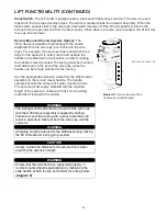
5F.2
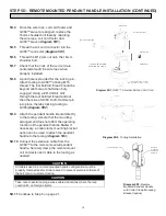
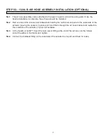
Grab the free end of the wire rope and loop it up
towards the underside of the actuator, ensuring there
are no twists or kinks in the rope. Feed the U-bolt
through the wire rope thimble and insert the U-bolt
into the appropriate holes in the reinforcement plate.
Using supplied hexnuts, securely tighten the U-bolt
to the plate (
diagram 5E2
, page 16).
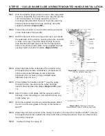
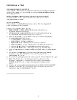
4X 65018
4X 65052
83255 (PULLEY)
83261 (BEARING)
65086 (SNAP RING)
2X 83259
2X 2001.12
83258
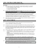
5F.3
Attach the plate to the underside of the actuator using the supplied cap screws, lockwashers and
spacers as shown and ensure hardware is completely tightened. (If an air hose is being installed,
leave hardware loose for now).
5F.4
Insert eyebolt at the end of the pendant cable into the threaded hole on the reinforcement plate
and tighten. Thread the coil cord connector into mating connector on the underside of the
actuator.
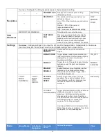
5F.5
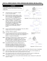
While holding the G360™, loop the pulley through the wire rope and slip the pulley and side
spacers down between the plates (
diagram 5E3
).
5F.6
Align the holes in the plates with the spacers and the bearing, insert the pulley pin, and install the
snap ring on the pulley pin.
5F.7
Using the supplied cap screws and lockwashers, attach the coil cord mounting plate to the top of
the G360™.
5F.8
Continue to Step 6 on page 21.
Diagram 5E3.
Attaching Wire Rope
to Pulley.
16


