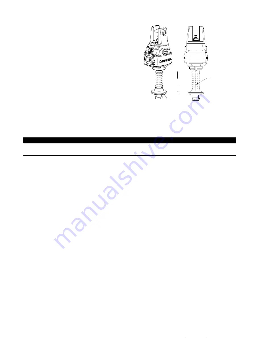
LIFT FUNCTIONALITY
Standard Operation - Slide Handle Configuration:
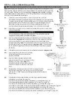
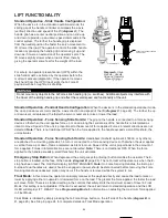
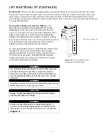
When the device is in the standard operational mode, the
sliding grip of the handle controller commands the z-axis
(vertical) direction and speed of the lift (
diagram A
). The
handle grip has a center neutral position and can slide up
and down to provide up and down speed commands to the
control system. The further the handle grip is displaced
from the neutral position the faster the servo movement to
lift or lower the load. The operator controls the slide handle
location by grasping the handle grip and moving it up and
down as if it were an extension of the
operator’s arm. The
lift moves slightly slower when a load is lifted, thereby
giving the operator some feel for the weight of the load.
HANDLE GRIP MOTION
HANDLE GRIP
OPERATOR PRESENT SENSOR
LINE OF SIGHT
For safety, an operator present sensor (OPS) within the
slide hand must be activated by the operator before the
motor will activate (diagram A). If the operator removes
their hand from the OPS’ line of sight, the G-Force®
payload with be brought to a safe stop.
WARNING
Do not mount any objects to the G-Force slide handle grip (i.e. switches). Additional objects may interfere with
the travel of the sliding handle grip and affect the overall speed and functionality of the unit.
Standard Operation - Pendant Handle Configuration:
When the device is in the standard operational mode,
the up and down levers command the z-axis direction and speed of the lift (
diagram C
, page 22). The further the up
or down lever is depressed, the faster the servo movement to raise or lower the load.
Standard Operation - Force Sensing Slide Handle:
The grip on the handle is connected to a force sensing
device so that when the user applies force up or down along the central axis of the handle this is interpreted as
intent to move. Speed of the unit is proportional to the amount of force applied. Forces in lateral directions are not
detected.
Note:
There is no traditional OPS. When the force applied to the handle exceeds a small threshold, the
unit activates.
Standard Operation - Force Sensing Hub Handle:
Handlebars (Gorbel® optional kit 74630, or by others)
are attached to a mounting plate which in turn is connected to a force sensing device so that when the user applies
a vertical force up or down, this is interpreted as intent to move. Speed of the unit is proportional to the amount of
force applied. Forces in lateral directions are not detected.
Note:
There is no traditional OPS. When the force
applied to the handle exceeds a small threshold, the unit activates.
Emergency Stop Button:
When depressed, the emergency stop (E-stop) button disables the actuator. The E-
stop button is located on the face of the handle (
diagram B
, page 26). The G-Force® will operate only when the E-
stop has been reset. The OLED will display E-STOP ENGAGED.
Note:
On Force Sensing Handles, the E-stop (or
E-stops if dual handles are used) should be engaged or power should be disconnected before removing the Force
Sensing Handle as undesired motion may occur if the handle is removed while the system is live.
Float Mode:
In this mode, the operator can simply maneuver the payload directly and cause the load to raise or
lower by applying either an upward or downward force on the load. The greater the force applied, the faster the load
will move. Note: There is a standard setting in the controls that safely limits the maximum speed of travel in Float
Mode; this setting is not adjustable. If the limit is exceeded, the unit will return to standard operation and the LCD
OLED will display LIFT READY. See
Programming Mode
for information on adjusting the maximum force applied
in Float Mode.
Float Mode is initiated by simply pressing the G-Force® logo button on the left side of the handle (
diagram B
or
C
, page 26). See Step 8, page 24, for complete details on Float Mode operation.
Diagram A.
Slide
Handle - Handle
Grip and Operator
Present Sensor
Li
f Si ht
24

