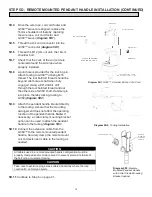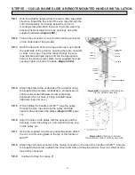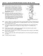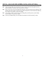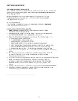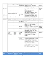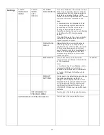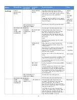
CONTROLS INTERFACE FEATURES
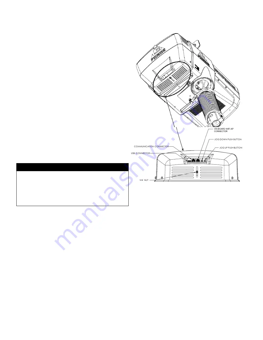
The jog switch push buttons and communica-
tions connector are protected by a cover
(
diagram E
). To access the jog switch push
buttons and communications connector, loosen
the M4 nut and slide the shield back towards
the wire rope.
Note:
Do not fully unthread the
M4 nut. When finished, slide the shield back
into place and re-tighten the M4 nut.
Jog Switch Push Buttons:
The jog switch
buttons allow qualified personnel to replace the
wire rope on the unit. To effectively operate the
jog switch buttons, all electrical cables must
be connected and power on. Depressing the
“Up” jog switch button will enable the motor and
cause the system to reel the wire rope into the
actuator and onto the drum pulley. Depressing
the “Down” jog switch button will enable the
motor and cause the system to pay out the wire
rope from the actuator and off of the main
pulley. Jog switch push buttons override all
motion control from a handle or tooling.
JOG DOWN PUSH BUTTON
JOG UP PUSH BUTTON
Diagram E.
Actuator - Controls Interface Display
(as viewed from bottom of actuator).
Service Mode:
This operation mode is similar to the “safe mode” of a PC. In this state all handle motion
control and Q2 & iQ2 custom features are disabled, all digital outputs are turned off, and only basic jog
up, jog down, OLED display and safety program mode are available. It allows a minimum safe operation
on a unit with a damaged handle, broken I/O electronics or other damaged peripheral control components
that would make it dangerous to run the unit if the component is used. The unit is still inoperative if
actuator components such as the drive, motor, or jog switches are damaged. To activate service mode,
with the handle E-stop pushbutton released and the OLED screen displaying LIFT READY, press and
hold both jog pushbuttons on the actuator for ten seconds. Both the blue and red LEDs flash once per
second and the OLED displays SERVICE MODE when the operation mode is ready.
Communications Connector:
This connector is the communications port for the G-Force®. With a
standard RJ45 Ethernet cable, users may connect to the G-Force® to upload software programs or use the
G-Force® VNC Viewer. When not in use, ensure the Jumper is connected between the Communications
Connector and the On-board WiFi AP Connector.
On-board WiFi AP Connector:
This is the port that connects the CPU of the G-Force® to the Access Point
located on the Actuator’s printed circuit board.
USB Connector:
This port is used to upload software programs to the G-Force® via a USB flash drive.
WARNING
The jog switch buttons are for system maintenance
and load testing use only and should not be
manipulated during normal operation of the
G-Force. Operation of the jog switch buttons
during normal operation increases the risk of
personal injury to the operator.
27


