DUAL HANDLE SETUP INSTRUCTIONS
1. Purpose
This section describes the procedure to setup multiple handles on the G-Force® Q2 and iQ2 products.
Additional usage notes reside within.
2. Scope
This procedure applies to both Q2 and iQ2 G-Force® and Easy Arm® products.
3. Prerequisites
SAFETY WARNING
: Activities described in this procedure can cause personal harm. The minimum
personal protective equipment (PPE) that must be worn at all times include safety glasses with side
shields and safety shoes. Additional PPE required for specific activities will be noted in the instruction.
Tools Used
:
•
Q2 or iQ2 G-Force® / Easy Arm®.
•
220VAC Power Supply to the G-Force®.
•
Two handles (Slide and/or Pendant ONLY).
•
Tools depend on Handle type, contact Gorbel® After the Sales Service for more info
disassembling the Handle.
4. Procedure
5.1 Setting up Handle Configurations:
Disconnect BOTH handles from the Actuator.
Handle 1:
•
Utilize the Gorbel® G-Force® Service Manual or Contact
Gorbel® After the Sales Service to access the Handle
Motherboards from the Housings.
•
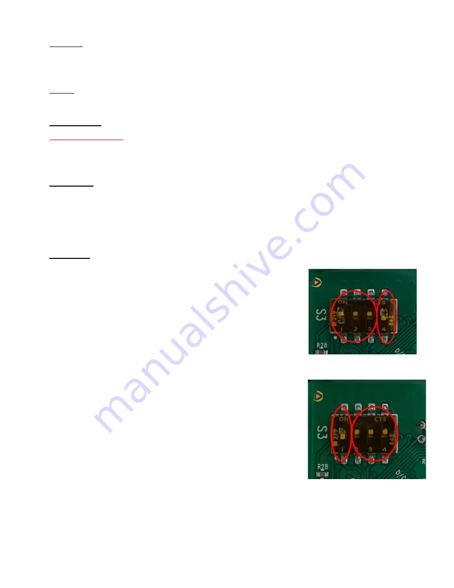
On the Handle Mother Board, go to the Block of 4 DIP
Switches, S3 to the right.
•
Using a precision screwdriver, toggle Switch 4 to the OFF
position and ensure all other switches are in the ON position.
NOTE:
When Switch 1 is in the ON position, the Handle is at Node 9 and
active.
When Switch 4 is in the OFF position, the Handle CAN
communication is not terminated and can therefore continue to the
next Handle Node
Handle 2:
Using the screwdriver, toggle switch 1 to the OFF position and
ensure all other switches are in the ON position.
60


