G-Force® & Easy Arm Q2 - iQ2 Service Manual
Gorbel Inc.
Revised 5/21
9 - 53
Removal & Replacement Procedures
FORCE SENSING HANDLE
Note: The following procedures assume any electrical or support cables have been disconnected prior to perform-
ing any repairs on the Pendant Handle itself.
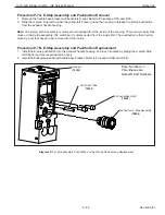
Procedure F-1A. Remote Mount Cap Sub-Assembly Removal
Note: This procedure assumes the handle has already been removed from a remote mount bracket or similar
mounting device.
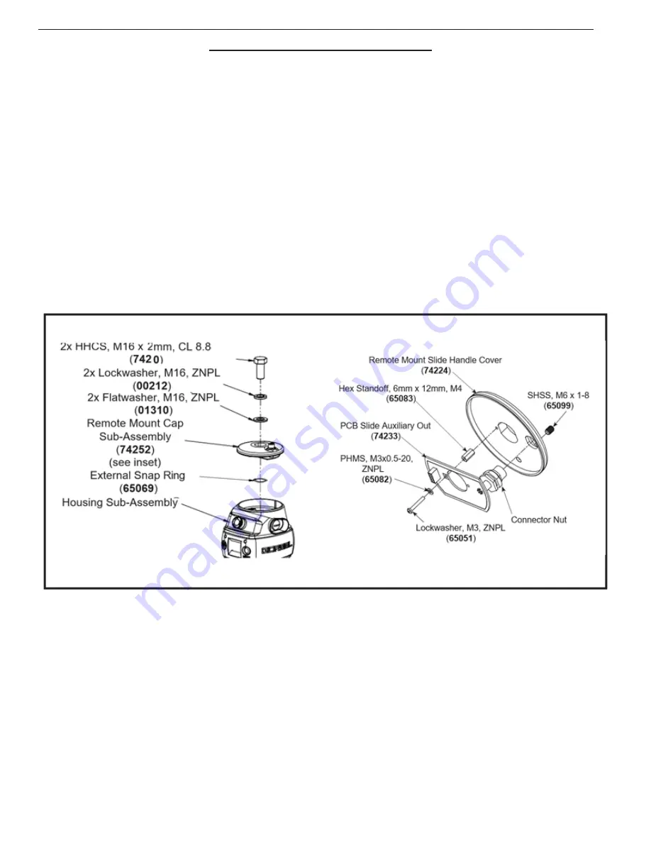
1. Remove M16 hex head cap screw (HHCS),
fl
atwasher and lockwasher from the top of the handle assembly.
2. Slide the remote mount cap o
ff
the handle shaft. Note the orientation of the internal electrical connector located
below the remote mount cap.
Procedure F-1B. Remote Mount Cap Sub-Assembly Replacement
1. Slide the remote mount cap onto the handle shaft. Note the orientation of the internal electrical connector locat-
ed below the remote mount cap.
2. Position the handle assembly into the remote mount bracket (if applicable) and install M16 hex head cap screw
(HHCS),
fl
atwasher and lockwasher onto the top of the handle assembly.
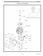
Diagram F-1
.
Remote Mounted Force Sensing Handle Remote Mount Cap Sub-Assembly Removal and
Replacement.
Note: See Procedure S-1 (Slide Handle) to view the removal/replacement of the swivel sub-as-
sembly. These are identical processes for Force Sensing Handles and Slide Handles.
(
74682 / 74683
)


