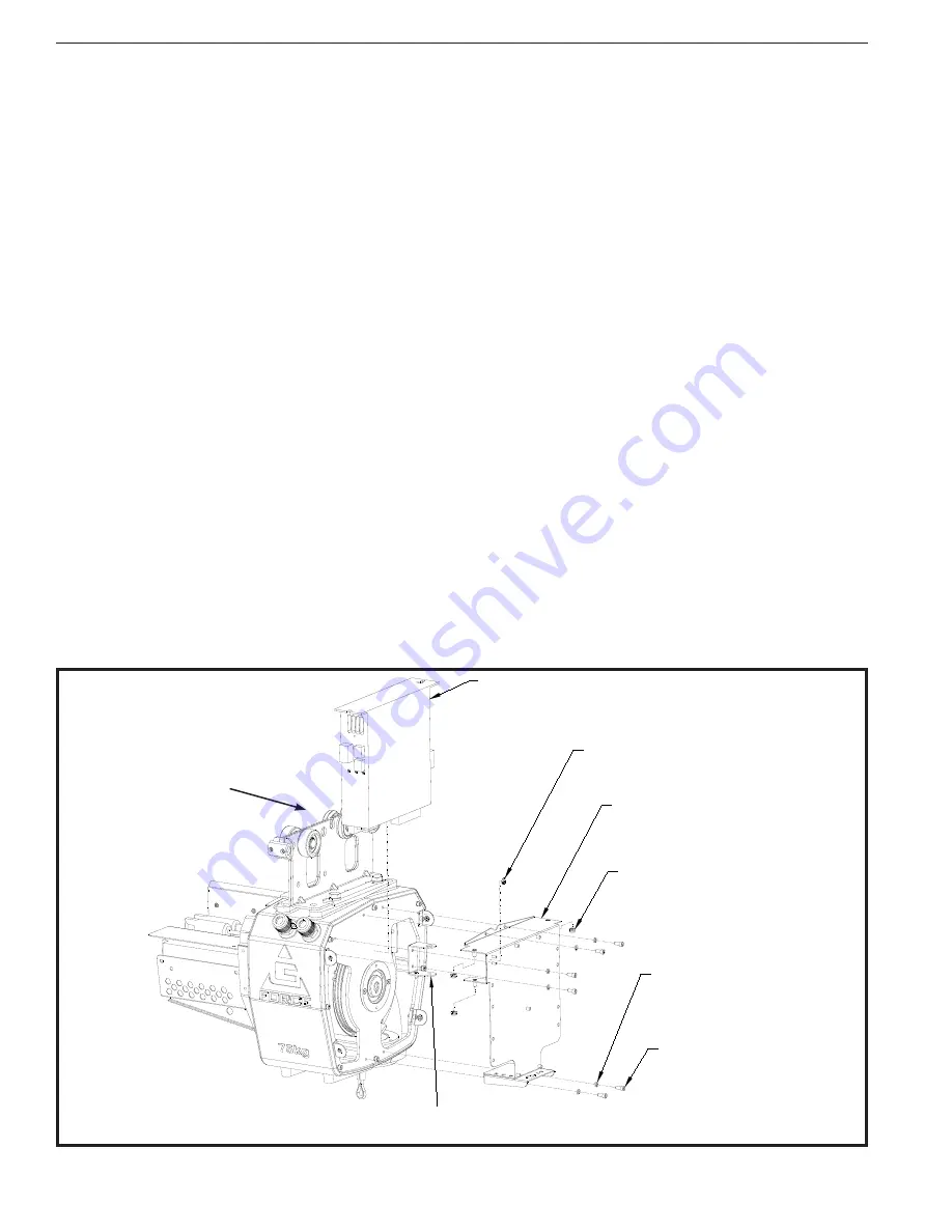
Procedure 6A - ACOPOS Support Bracket & ACOPOS Servo Drive Removal
1. Turn power o
ff
by disconnecting AC power to the system.
2. Remove front cover. Refer to Procedure 1A.
3. Remove electrical shield. Refer to Procedure 3A.
4. Remove main PCB. Refer to Procedure 4A.
5. Remove (2) M5 button head cap screws (BHCS) and M5 lockwashers from top portion of PCB / ACOPOS sup-
port bracket.
6. Remove (2) M5 button head cap screws (BHCS) and M5 lockwashers from lower portion of support bracket.
7. Disconnect all external cable assemblies from the ACOPOS drive, and release from latching wire clips. Note the
cable numbers for cable assemblies that connect to J4, J6, J9, J13, J14 and J15.
8. Remove (2) M6 Nylock nuts from hinge pins.
9. Lift PCB / ACOPOS support bracket, with ACOPOS drive still attached, o
ff
hinge bracket.
10. Separate the ACOPOS servo drive from the PCB / ACOPOS support bracket assembly by removing the (2) M6
Nylock nuts from the underside of the upper portion of the PCB / ACOPOS support bracket assembly.
Procedure 6B - ACOPOS Support Bracket & ACOPOS Servo Drive Replacement
1. Attach ACOPOS servo drive to PCB / ACOPOS support bracket with the (2) M6 Nylock nuts.
2. Position PCB / ACOPOS support bracket with ACOPOS servo drive attached onto hinge bracket and install (2)
M6 Nylock nuts.
3. Swing ACOPOS assembly into its normal operating position. Install all the cable assemblies to the ACOPOS
servo drive, and secure into latching wire clips. Check the cable numbers for cable assemblies that connect to
J4, J6, J9, J13, J14 and J15.
4. Install (2) M5 button head cap screws (BHCS) and M5 lockwashers into top portion of PCB / ACOPOS support
bracket.
5. Install (2) M5 button head cap screws (BHCS) and M5 lockwashers into lower portion of PCB / ACOPOS sup-
port bracket.
6. Install main PCB. Refer to Procedure 4B.
7. Install electrical shield. Refer to Procedure 3B.
8. Install front cover. Refer to Procedure 1B.
9. Restore AC power to the system.
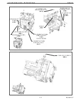
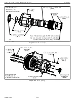
ACOPOS Servo Drive, 110-230 VAC, 1 Phase
(
78585
)
Ground Warning Label
(
77072
)
ACOPOS Pivot Bracket
(
79262
)
PCB/ACOPOS Support
Bracket Assy
(
79243
)
6x Lockwasher, M5,
High-Collar
(
65062
)
6x SHCS, M5 x 12mm Lg
(
65002
)
4x Nylock Nut, M6, ZNPL
(
65090
)
AC114 Card (
78587
)
AC122 Card (
78552
)
AC131 Card (
78553
)
Diagram 6. ACOPOS and Support Bracket Removal and Replacement.
Note
:
P/N 78585
includes AC114,
AC122 and AC131
pwbs
G-Force® & Easy Arm Q2 - iQ2 Service Manual
Gorbel Inc.
Revised 5/21
9 - 9


