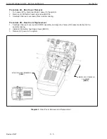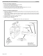
Procedure 7A - CPU Assembly Removal
1. Turn power o
ff
by disconnecting AC power to the system.
2. Remove rear cover. Refer to Procedure 2A.
3. Loosen End Block to the right of CPU and slide CPU about 3 inches to the right.
4. Disconnect all cable assemblies from the CPU. Note the cable numbers for cable assemblies that connect to
IF2 & IF3.
5. If this is an iQ2 model it may be necessary to disconnect the terminal block for any I/O wiring from the I/O mod-
ule.
6. Lift (2) Orange tabs releasing CPU from DIN rail and lift CPU o
ff
bracket.
Procedure 7B - CPU Assembly Replacement
1. Position CPU on DIN Rail close to the center casting.
2. Press (2) Orange tabs locking CPU onto DIN rail and gently tug CPU to ensure proper connection to bracket.
3. Connect all cable assemblies to CPU and any I/O wiring, if necessary. Check the cable numbers for cable as-
semblies that connect to IF2 & IF3.
4. Slide CPU & right end clamp terminal block back to the left until it contacts the left end clamp terminal block and
retighten the right end clamp terminal block.
5. Reinstall rear cover. Refer to Procedure 2B.
6. Restore AC power to the system.
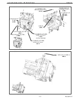
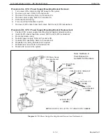
Diagram 7.
CPU Removal & Replacement
2X END BLOCK
(
80360
)
Q2 CPU: (
78510
)
SLACK SPRING
(
79237
)
SLACK SPRING EYE BOLT
(
79210
)
NYLOCK NUT, M6, ZNPL
(
65090
)
HEXNUT, M6, ZNPL
(
01764
)
POWER SUPPLY
(
78574
)
POWER SUPPLY HARDWARE
DIN RAIL
(
76543
)
2X M6X10 BHCS
(
65076
)
ENSURE THE CAN TERMINATION
RESISTOR IS IN THE ‘ON’ POSITION
G-Force® & Easy Arm Q2 - iQ2 Service Manual
Gorbel Inc.
Revised 5/21
9 - 10


