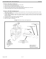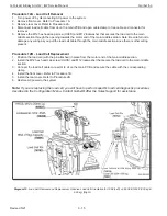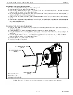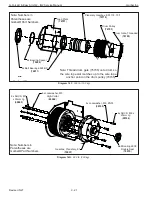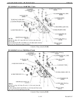
iQ2 CPU
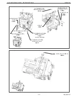
To add the CPU I/O Slice:
1. Loosen the End Block
80360,
and slide it to the right, then slide it o
ff
the Orange Right Side Cover.
2. Depress the tab on the face of the Terminal Block,
78509
, swinging it down to
≥
90° to remove from the CPU,
78519.
3. Take the Backplane,
78515
, and lift the Orange Lever Tab on top until it clicks into the unlocked position. Then,
align it with the slots in the CPU,
78510
, and
FIRMLY
press it against the CPU while sliding it toward the Din Rail.
4. Take the I/O Slice,
78516
, and slide it into the Backplane,
78515
, ensuring that the I/O Slice is
fl
ush with the face
of the CPU,
78510
.
5. MAKE SURE THERE IS NO GAP BETWEEN THE I/O SLICE,
78516
, AND THE CPU,
78510.
If there is a gap,
start over at step 1.
6. Latch the Backplane,
78515
, onto the Din Rail by lowering the Orange Lever Tab until it clicks into the locked
position.
7. Replace the Terminal Block,
78509
, onto the CPU by aligning the Terminal Block’s hook with the pin a the base
of the CPU,
78510,
creating a hinge. Then, swing it upward until it clicks into place. Repeat this for the new I/O
Terminal Block,
78509.
8. Slide on the Orange Right Side Cover and resecure the End Block,
80360
,
next to the CPU.
9. Insert USB Dongle,
78518,
into the available USB port on the CPU,
78510.
P/N
DESCRIPTION
QTY.
78509
X20 TERMINAL BLOCK, 12-PIN
1
78518
USB DONGLE
1
78516
I/O SLICE
1
78515
BACKPLANE
1
G-Force® & Easy Arm Q2 - iQ2 Service Manual
Gorbel Inc.
Revised 5/21
9 - 11
78510
78518
78509
78516
78515
80360


