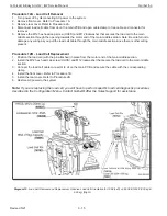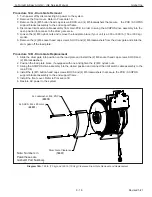
Procedure 13A - Drum Cover and Drum Cover Band Removal
1. Turn power o
ff
by disconnecting AC power to the system.
2. Remove front cover. Refer to Procedure 1A.
3. Remove end support frame. Refer to Procedure 9A.
Note: Use caution during the next step. The drum cover band will be in tension.
4. Remove the (2) M6 socket head cap screws (SHCS) and M6 lockwashers that secure the drum cover band to
the load plate.
5. Slide both the drum cover band and drum cover o
ff
the drum pulley.
Procedure 13B - Drum Cover and Drum Cover Band Replacement
1. Position the drum cover band inside the drum cover and slide the assembly over the drum pulley.
2. Install the (2) M6 socket head cap screws, SHCS and (2) M6 lockwashers for the drum cover band into the load
plate.
3. Install the end support frame. Refer to Procedure 9B.
4. Install the front cover. Refer to Procedure 1B.
5. Restore power to the system.
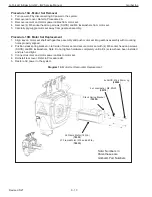
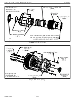
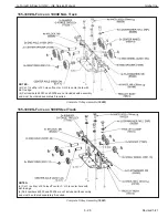
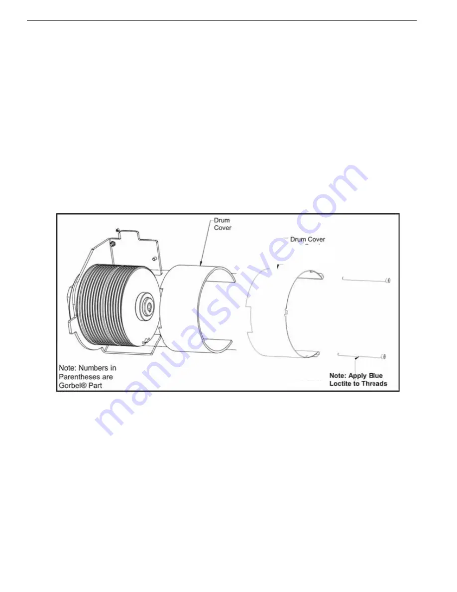
Diagram 13a. Drum Cover and Band Removal and Replacement.
Notes:
a.
165 lb. (75 kg) and 330 lb. (150 kg) units use Drum Cover (76703), Drum Cover Band (76702), and
2x SHCS, M6 x 110mm Lg (65037).
b.
660 lb. (300 kg) units use Drum Cover (76513), Drum Cover Band (76509), and 2x SHCS, M6 x
90mm Lg (65030).
See notes below
G-Force® & Easy Arm Q2 - iQ2 Service Manual
Gorbel Inc.
Revised 5/21
9 - 17


