G-Force® & Easy Arm Q2 - iQ2 Service Manual
Gorbel Inc.
Revised 5/21
9 - 18
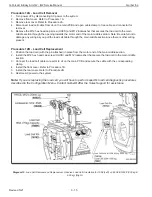
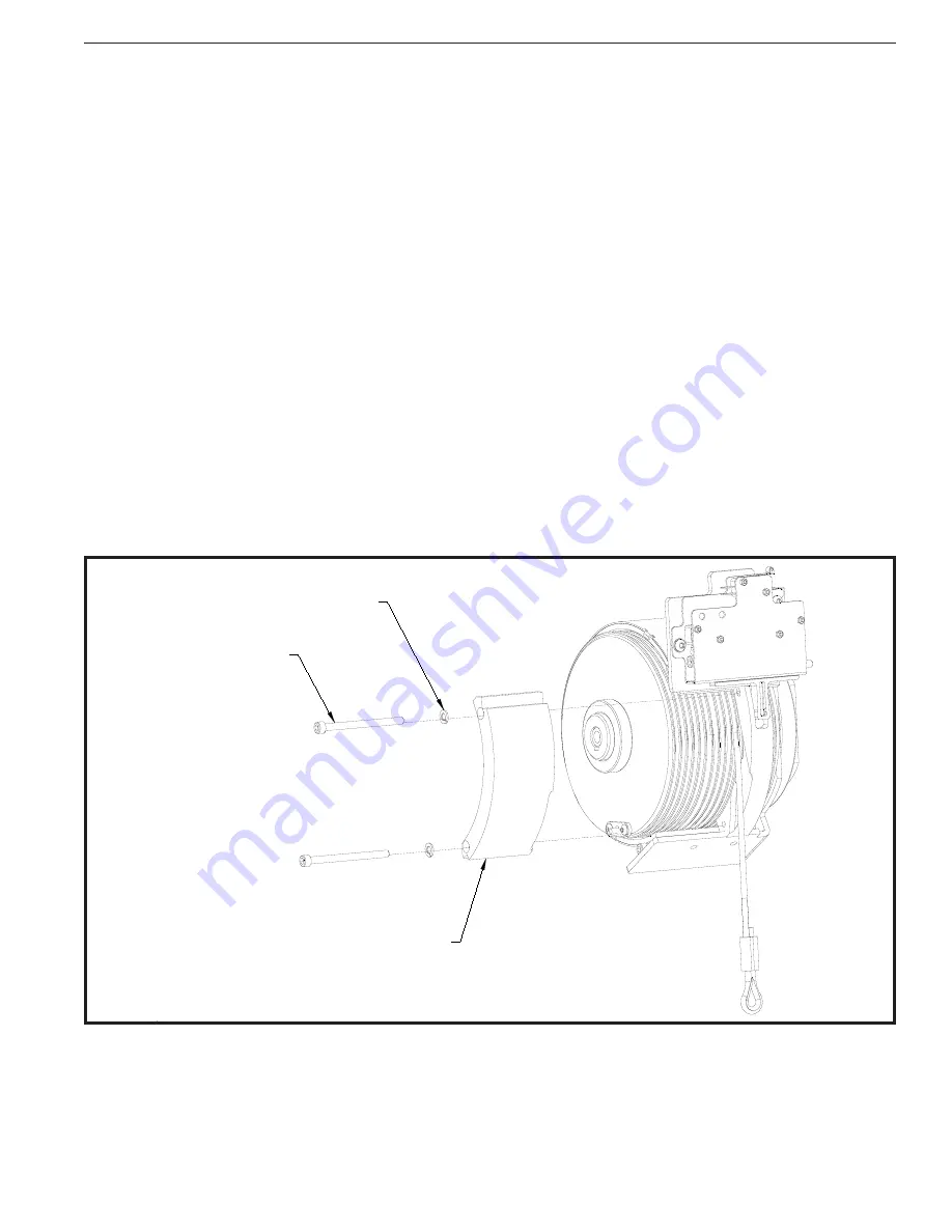
Procedure 14A - Drum Gate Removal
1. Turn power off by disconnecting AC power to the system.
2. Remove the front cover. Refer to Procedure 1A.
3. Remove the (4) M5 button head cap screws, BHCS and (4) M5 lockwashers that secure the PCB / ACOPOS
support bracket assembly to the end support frame.
4. Disconnect limit switch cable assembly from main PCB in order to swing the ACOPOS drive assembly into the
open position for access to the drum gate area.
5. Loosen the (2) M8 nylock nuts and remove the load plate brace if your unit is a 330 or 660 lb. (150 or 300 kg)
model.
6. Remove the (2) M6 socket head cap screws, SHCS and (2) M6 lockwashers from the drum gate and slide the
drum gate off the load plate.
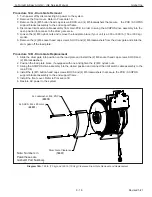
Procedure 14B - Drum Gate Replacement
1. Slide the drum gate into position on the load plate and install the (2) M6 socket head cap screws, SHCS and
(2) M6 lockwashers.
2. Position the load plate brace if equipped with one and tighten the (2) M8 nylock nuts.
3. Swing the ACOPOS drive assembly into the closed position and connect the limit switch cable assembly to the
main PCB.
4. Install the (4) M5 button head cap screws, BHCS and (4) M5 lockwashers that secure the PCB / ACOPOS
support bracket assembly to the end support frame.
5. Install the front cover. Refer to Procedure 1B.
6. Restore AC power to the system.
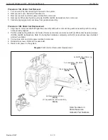
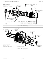
Diagram 14A. 165 lb. (75 kg) and 330 lb. (150 kg) Clearance Drum Gate Removal and Replacement.
Drum Gate Clearance
(
76537
)
2x SHCS, M6 x 80mm Lg
(
65031
)
2x Lockwasher, M6, ZNPL
(
03370
)
Note: Numbers in
Parentheses are
Gorbel® Part Numbers

