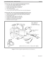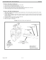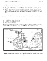
G-Force® & Easy Arm Q2 - iQ2 Service Manual
Gorbel Inc.
Revised 5/21
9 - 23
Procedure 15A - Limit Switch Assembly Removal
1. Turn power o
ff
by disconnecting AC power to the system.
2. Remove front cover. Refer to Procedure 1A.
3. Disconnect the limit switch cable assembly from the main PCB (J11).
4. Remove the access plug from the main middle section.
5. Remove the M6 button head cap screw (BHCS) and M6 lockwasher from the main PCB end of the limit switch
assembly.
6. Remove the limit switch assembly from the load plate inside the main middle section.
Procedure 15B - Limit Switch Assembly Replacement
1. Position the limit switch assembly on the load plate by locating it on the inside M6 button head cap screw
(BHCS). The lower projection of the slide must be engaged in the recess in the threaded gate.
2. Install the M6 button head cap screw (BHCS) and M6 lockwasher on the main PCB end of the limit switch as-
sembly.
3. Connect the limit switch cable assembly to the main PCB (J11).
4. Install the access plug into the main middle section.
5. Install the front cover. Refer to Procedure 1B.
6. Restore AC power to the system.
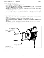
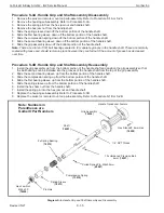
Diagram 15. Limit Switch Assembly Removal and Replacement
.
Note: Numbers in
Parentheses are
Gorbel® Part Numbers
Limit Switch Assembly
(
79277
)
Note:
Slide limit switch
assembly into place on
load plate. The M6 BHCS
will retain one end and the
M6 SHCS, shown below,
will retain
the other.
BHCS, M6 x 16mm Lg
(
65075
)
Lockwasher, M6, ZNPL
(
03370
)


