G-Force® & Easy Arm Q2 - iQ2 Service Manual
Gorbel Inc.
Revised 5/21
9 - 46
Procedure P-7A. E-Stop Assembly and Pushbutton Removal
1. Remove the handle base bracket and backplate & seal. Refer to Procedures P-3A and P-4A.
2. Slide the metal E-stop latch (under the yellow latch cover) inside the housing to release the E-stop pushbutton
from the pendant handle housing.
Note: The E-stop button assembly is removed and installed from the inside of the housing. There are two parts that
make up the E-stop assembly. The switch part is disconnected from the inside fi rst. The pushbutton is then held in
place by a nut that needs to be removed from the inside.
Procedure P-7B. E-Stop Assembly and Pushbutton Replacement
1. Install the E-stop pushbutton into the pendant handle housing, and lock into place by sliding the metal E-Stop
latch back (and secure yellow latch cover).
2. Install the backplate & seal and handle base bracket. Refer to Procedure P-3B and P-4B.
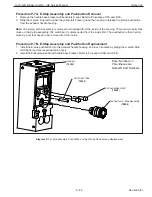
Diagram P-7. E-Stop Assembly, Pushbutton and Light Tube Removal and Replacement
Housing
(
74302
)
LED Light Tube
(
74320
)
2x Pushbutton Shaft
(
74309
)
Pushbutton, E-Stop Assembly
(
78804
)
Note: Numbers in
Parentheses are
Gorbel® Part Numbers


