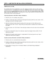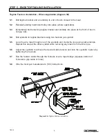
TORQUE CHECKING
To check the Torque Limiter for the required slip torque, mount the Torque Limiter on a stub
shaft and fasten in a bench vise. Wrap the center member (if a sprocket) with a chain and load
the chain with weights until the center member rotates. If the center member is a plate, attach a
chain or cable to the center member. The breakaway torque will be equal to the radius of the
center member in feet times the weight in lbs. on the chain. The breakaway torque should be
slightly higher (5% to 10%) than the required slip torque. If the slip torque is too high or too low,
readjust torque limiter as per torque setting procedures above. After readjustment, check the
breakaway torque in the manner outlined above and repeat adjustments is necessary
MAINTENANCE:
The Securex series torque limiters do not normally require any maintenance. However, as with
all friction torque limiters, regular inspection of the friction surfaces and other related
components is highly recommended. The friction pads should be replaced when they have
each worn to half of their original, new thickness. At periodic intervals, or if proper torque is not
being maintained, inspect Torque Limiter for presence of oil, grease, moisture, or corrosion on
the driving surfaces and for proper setting of spring load. Clean and adjust as required. Friction
facings and bushings are the only parts that should normally require replacement.
CAUTION
The operating characteristics and capacity of Torque Limiters are affected by atmospheric
conditions, moisture, lubricants, and surface corrosion. To illustrate, the life of the friction facings
may be greatly reduced by rust on the center plate. The Torque Limiter ratings are based on
average conditions. For best results, the Torque Limiter should be adjusted under conditions like
those in which it will be used.
HOW TO REPLACE FRICITON DISCS
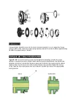
Please refer to the appropriate sketch (see above).
1.
Remove the drive chain/belt from the torque limiter center member.
2.
Loosen
Adjusting nut (J)
3.
Disassemble all components in the following order: Remove
(G) Pilot plate (95 to 170 size
models only) or (H) Lock washer (30 to 85 size models only), (F) Spring(s), (E) Pressure plate,
(D) Friction facing, (C) Center member (not shown), (B) Bushing, and (A) Friction facing
4.
Reassemble by placing new friction discs on both sides of a new sprocket and a new
sintered bushing. Please refer to the assembly instructions above.

