6
9/18 Rev. F
Splice Joint Instructions
4.6
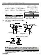
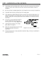
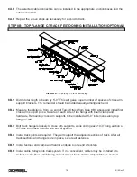
Bring the ends of the track sections together as close as possible (
diagram 4C
).
4.7
Align holes in washer plate with the slots in the top flange of the rail. Tighten beam clamp
hardware. This will help align the top flange portion of track sections (
diagram 4D
).
4.8
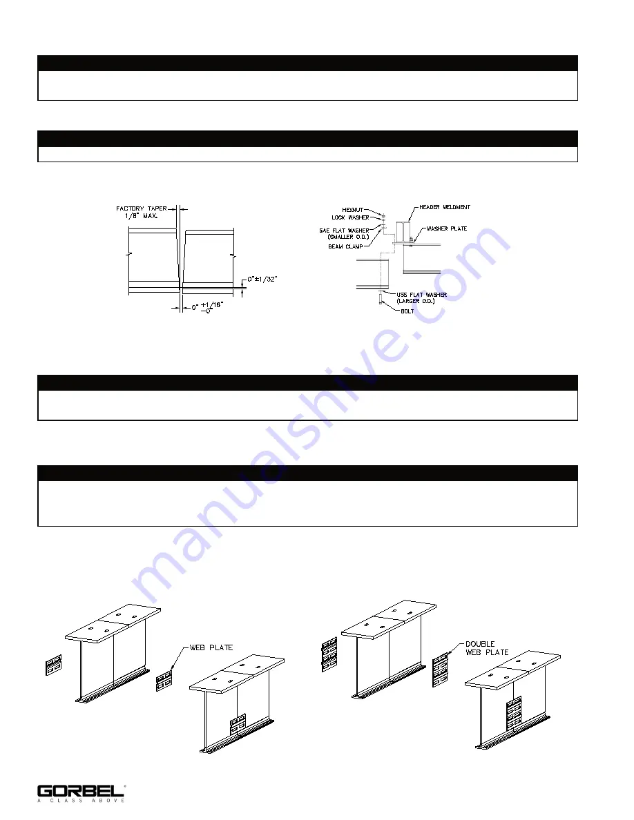
Place web splice plate(s) on each side of web section. Align plate as shown (
diagrams
4E
and
4F
for welded splice or
diagrams 4H
and
4J
for bolted splice).
4.9
Web splice plates to be welded in accordance with American Welding Society (AWS)
specification D1.1 using E70xx electrodes (
diagram 4G
).
4.10
Check to see that the transition from one track to the other is smooth: no raised areas to
inhibit carrier or end truck operation (
diagram 4C
).
4.11
For additional runways repeat Steps 4.6 through 4.10.
WARNING
Reference the General Arrangement Drawing for splice locations. It will be necessary to install
adjacent runways at the same time.
WARNING
Track sections and web plate need to be carefully aligned before field welding of plates to
allow smooth transition between sections.
Diagram 4E.
Welded splice (4200-4600 Tarca® beam).
Diagram 4F.
Welded splice (5000 & Larger Tarca® beam).
WARNING
If welding of lower track is desired (not required), different electrodes are required for mild steel
vs. hardened steel. E7018 is used for mild steel only (web and top flange). E11018 must be
used for hard steel and may also be used for mild steel.
Diagram 4C.
Rail Alignment.
Diagram 4D.
Attaching header to top flange.
WARNING
If shimming runway, shim must be located between washer plate and top of runway.


