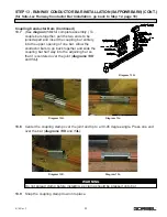
STEP 5 - RUNWAY AND BRIDGE END STOP INSTALLATION (CONTINUED)
5.2
The standard end stops are for normal
applications where contacts with end stops are
infrequent and travel is at slow speed.
5.3
When service conditions are such that the
carrier, trolley, or crane will contact the end stop
frequently or at high speed, spring bumpers or
other energy absorbing type end stops are
available and should be used. For their
application and detail contact our Inside Sales
Department.
STEP 6 - BRIDGE AND END TRUCK INSTALLATION
FIRST STEPS:
6.1
Prior to adding bridge, wipe rail tread with a clean, dry
cloth to remove grit or debris that may have collected
during shipping, storage, or installation.
6.2
Lay bridge girder on floor. Stabilize the girder so that it
cannot tip over.
6.3
Place endtrucks on top flange of girder and orient them so that the motors will be in the
desired location (
diagram 6A
- solid lines indicate standard motor position). Center the
endtruck to bridge connection bolt pattern on the girder. Make sure that the bridge span
exactly matches the distance between runway centerlines. Also confirm that the endtrucks
are square to the girder by matching diagonal measurements.
6.4
Transpose the bolt pattern from endtruck to bridge girder. Match mark endtrucks and
bridge.
6.5
Drill bolt holes (Ø 49/64”).
6.6
Bolt endtrucks into place. Confirm that the bridge span is correct and endtrucks are
square.
Diagram 6A.
If customer is supplying bridge, go to step 6.2. If
endtrucks and bridge are ordered together, start at
step 6.9.
Chart 5A.
Torque Chart.
9
9/18 Rev. F


