STEP 10 - BRIDGE GIRDER CONDUIT INSTALLATION
10.1
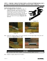
If not already installed by Gorbel, secure EMT conduit below top flange of girder avoiding
trolley interference. Conduit is shipped in 10 ft. lengths to be cut as needed.
10.2
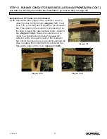
Flexible conduit to be mated to EMT conduit with connectors provided.
10.3
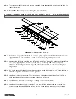
Flexible conduit to be routed as shown (
Diagram 10A
) into either side of control
enclosure.
10.4
NOTE:
If splicing of the wire is necessary, a junction box will be required. An EMT / flex
connection can be used with a continuous length of wire from enclosure to motor.
TIP:
If requested, Gorbel can install the rigid conduit on the bridge girder. Installer will be
responsible for attaching control enclosure (Step 9) and making all flexible conduit
connections. Reference Step 11 for motor wiring.
Diagram 10A.
Bridge conduit wiring diagram.
16
9/18 Rev. F


