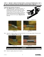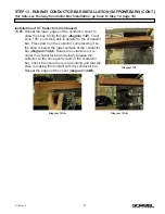
STEP 13 - RUNWAY CONDUCTOR BAR INSTALLATION (SAFPOWRBAR®)
(for Safe-Lec Runway Conductor Bar Installation, go back to Step 12, page 18)
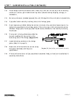
Mounting Insulating Cover on Bar
13.1
Under normal circumstances the insulating cover will be shipped mounted on the bar, but
in case removal or replacement is necessary, the following procedure is suggested.
13.2
Starting the cover 2-1/8” down from the end of the bar and flat on top of the bar, mold the
cover down over the bar and work the lips of the cover over the legs of the bar. The
conductor bar is furnished in lengths of 21’-0” and the cover is furnished in lengths of
20’-7-3/4” which allows 2-1/8” of the bar to extend beyond the cover at each end. The
cover fits tightly on the bar and does not require any additional clamps to hold it in place.
Conductor Bar Mounting and Brackets
13.3
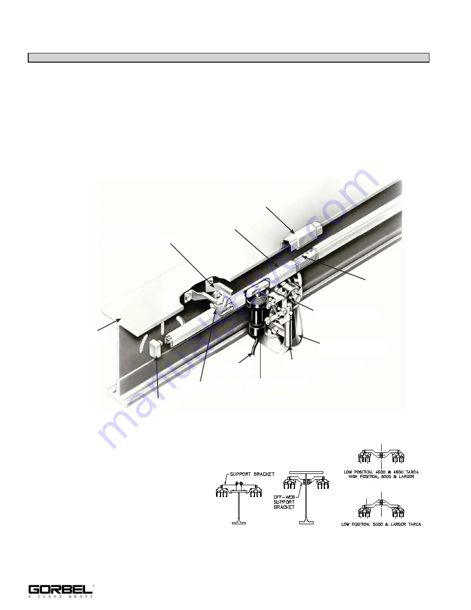
The conductor bar is held on by
insulators which are attached to
mounting brackets (
diagram 13A
).
There are two types of mounting
brackets as shown in
diagram
13B
.
20
9/18 Rev. F
Diagram 13A.
Coupling Cover
Coupling
SAFPOWRBAR®
Tarca® Beam
Offweb Support Bracket
End Cap
Support Insulator
Collector Lead
Type ST Collector
Collector Bracket
Idler Head
Collector Shoe
Diagram 13B.


