background image

LIMITED WARRANTY

It is agreed that the equipment purchased hereunder is subject to the following LIMITED warranty and no other.  Gorbel warrants the manual or motorized Patented 

Track Crane products to be free from defects in material or workmanship for a period of two years or 4,000 hours use from date of shipment in class C service. This 

warranty shall not cover failure or defective operation caused by operation in excess of recommended capacities, misuses, negligence or accident, and alteration or 

repair not authorized by Gorbel. No system shall be field modified after manufacture without the written authorization of Gorbel, Inc. Any field modification made to the 

system without the written authorization of Gorbel, Inc. shall void Gorbel’s warranty obligation. OTHER THAN AS SET FORTH HEREIN, NO OTHER EXPRESS

WARRANTIES, AND NO IMPLIED WARRANTIES, ORAL OR WRITTEN, INCLUDING BUT NOT LIMITED TO THE WARRANTIES OF MERCHANTABILITY OR

FITNESS FOR A PARTICULAR PURPOSE, ARE MADE BY GORBEL WITH RESPECT TO ITS PRODUCTS AND ALL SUCH WARRANTIES ARE HEREBY

SPECIFICALLY DISCLAIMED. GORBEL SHALL NOT BE LIABLE UNDER ANY CIRCUMSTANCES FOR ANY INCIDENTAL, SPECIAL AND/OR CONSEQUENTIAL 

DAMAGES WHATSOEVER, WHETHER OR NOT FORESEEABLE, INCLUDING BUT NOT LIMITED TO DAMAGES FOR LOST PROFITS AND ALL SUCH

INCIDENTAL, SPECIAL AND/OR CONSEQUENTIAL DAMAGES ARE HEREBY ALSO SPECIFICALLY DISCLAIMED. Gorbel’s obligation and Purchaser’s or end 

user’s sole remedy under this warranty is limited to the replacement or repair of Gorbel’s products at the factory, or at the discretion of Gorbel, at a location designated 

by Gorbel.  Purchaser or end user shall be solely responsible for all freight and transportation costs incurred in connection with any warranty work provided by Gorbel 

hereunder.  Gorbel will not be liable for any loss, injury or damage to persons or property, nor for damages of any kind resulting from failure or defective operation 

of any materials or equipment furnished hereunder. Components and accessories not manufactured by Gorbel are not included in this warranty.  Purchaser’s or end 

user’s remedy for components and accessories not manufactured by Gorbel is limited to and determined by the terms and conditions of the warranty provided by the 

respective manufacturers of such components and accessories.


A)  DISCLAIMER OF IMPLIED WARRANTY OF MERCHANTABILITY


Gorbel and Purchaser agree that the implied warranty of merchantability is excluded from this transaction and shall not apply to the goods


involved in this transaction.


B)  DISCLAIMER OF IMPLIED WARRANTY OF FITNESS FOR PARTICULAR PURPOSE


Gorbel and Purchaser agree that the implied warranty of fitness for particular purpose is excluded from this transaction and shall not apply to


the goods involved in this transaction.


C)  DISCLAIMER OF EXPRESS WARRANTY


Gorbel’s agents, or dealer’s agents, or distributor’s agents may have made oral statements about the machinery and equipment described in


this transaction. Such statements do not constitute warranties, and Purchaser agrees not to rely on such statements. Purchaser also agrees


that such statements are not part of this transaction.


D)  DISCLAIMER OF SPECIAL, INCIDENTAL AND CONSEQUENTIAL DAMAGES


Gorbel and Purchaser agree that any claim made by Purchaser which is inconsistent with Gorbel’s obligations and the warranty remedies


provided with Gorbel’s products, and in particular, special, incidental and consequential damages, are expressly excluded.


E)  DEALER OR DISTRIBUTOR NOT AN AGENT


Gorbel and Purchaser agree that Purchaser has been put on notice that dealer or distributor is not Gorbel’s agent in any respect for any


reason. Gorbel and Purchaser also agree that Purchaser has been put on notice that dealer or distributor is not authorized to incur any


obligations or to make any representations or warranties on Gorbel’s behalf other than those specifically set forth in Gorbel’s warranty provided


in connection with its product.


F) MERGER


This warranty agreement constitutes a final and complete written expression of all the terms and conditions of this warranty and is a complete


and exclusive statement of those terms.


G) PAINTING


Every crane (excluding components) receives a quality paint job before leaving the factory. Unfortunately, no paint will protect against the


abuses received during the transportation process via common carrier. We have included at least one (1) twelve ounce spray can for touchup


with each crane ordered (unless special paint was specified). If additional paint is required, contact a Gorbel® Customer Service


Representative at 1-800-821-0086 or 1-585-924-6262.

Title and Ownership:


Title to the machinery and equipment described in the foregoing proposal shall remain with Gorbel and shall not pass to the Purchaser until the full amount


herein agreed to be paid has been fully paid in cash.

Claims and Damages:


Unless expressly stated in writing, goods and equipment shall be at Purchaser’s risk on and after Seller’s delivery in good shipping order to the Carrier. Gorbel


shall in no event be held responsible for materials furnished or work performed by any person other than it or its authorized representative or agent.

Cancellations:


If it becomes necessary for the purchaser to cancel this order wholly or in part, he shall at once so advise Gorbel in writing. Upon receipt of such written notice


all work will stop immediately. If the order entails only stock items, a flat restocking charge of 15% of the purchase price will become due and payable by


Purchaser to Gorbel. Items purchased specifically for the canceled order shall be charged for in accordance with the cancellation charges of our supplier plus


15% for handling in our factory. The cost of material and/or labor expended in general fabrication for the order shall be charged for on the basis of total costs to


Gorbel up to the time of cancellation plus 15%.

Returns:


No equipment, materials or parts may be returned to Gorbel without express permission in writing to do so.


Extra Charge Delay: If Purchaser delays or interrupts progress of Seller’s performance, or causes changes to be made, Purchaser agrees to reimburse Gorbel


for expense, if any, incident to such delay.

Changes and Alterations:


Gorbel reserves the right to make changes in the details of construction of the equipment, as in its judgment, will be in the interest of the Purchaser; will make


any changes in or additions to the equipment which may be agreed upon in writing by the Purchaser; and Gorbel is not obligated to make such changes in


products previously sold any customer.

Third Party Action:


Should Gorbel have to resort to third party action to collect any amount due after thirty (30) days from date of invoice, the Purchaser agrees to pay collection


costs, reasonable attorney’s fees, court costs and legal interest.

OSHA Responsibilities:


Gorbel agrees to fully cooperate with Purchaser in the design, manufacture or procurement of safety features or devices that comply with OSHA regulations. In


the event additional equipment or labor shall be furnished by Gorbel, it will be at prices and standard rates then in effect, or as may be mutually agreed upon at


the time of the additional installation.

Equal Employment Opportunity: 


Gorbel agrees to take affirmative action to ensure equal employment opportunity for all job applicants and employees without regard to race, color, age, religion,


sex, national origin, handicap, veteran, or marital status. Gorbel agrees to maintain non-segregated work facilities and comply with rules and regulations of the


Secretary of Labor or as otherwise provided by law or Executive Order.

31

9/18 Rev. F

Summary of Contents for Tarca System

Page 1: ...IMPORTANT DO NOT DESTROY Installation Operation Maintenance Manual Month Year Gorbel Dealer Date Totally Free Standing Tarca System Gorbel Customer Order No Serial No Issued 06 2010 Revised 03 2019...

Page 2: ...This page intentionally left blank...

Page 3: ...13 15 Step 9 Enclosure Mounting Detail Pre Assembled 15 Step 10 Bridge Girder Conduit Installation 16 Step 11 Motor Wiring 17 Step 12 Runway Conductor Bar Installation Safe Lec 18 19 Step 13 Runway C...

Page 4: ...This page intentionally left blank...

Page 5: ...adequacy or integrity of the mounting surfaces or the structure that the crane may be mounted to Gorbel Inc will not be liable for any loss injury or damage to persons or property nor for damages of a...

Page 6: ...d Track Bridge Crane foundation requirements are based on a minimum soil pressure of 2500 per square foot Concrete should be a minimum of 3000 per square inch of compressive concrete Columns should be...

Page 7: ...facturer Vacuum or brush away cement dust 2 4 Install anchor bolts not included and hardware according to manufacturer s installation directions and requirements 2 5 Check to see if column weldment is...

Page 8: ...WARNING There must be a minimum of two threads showing at the end of the bolt Diagram 3B Installing header weldments Diagram 3A Header length Diagram 3C Beam Clamp Installation TIP 10 tall wide flang...

Page 9: ...ighten hardware chart 3A page 4 for proper torque rating 4 5 If you DO NOT have additional runways to install proceed to Step 5 1 on page 8 otherwise proceed to Step 4 6 on page 6 Diagram 4A Attaching...

Page 10: ...inhibit carrier or end truck operation diagram 4C 4 11 For additional runways repeat Steps 4 6 through 4 10 WARNING Reference the General Arrangement Drawing for splice locations It will be necessary...

Page 11: ...AY INSTALLATION CONTINUED Diagram 4G Splicing Runways together 7 9 18 Rev F Diagram 4H Bolted splice 4200 4600 Tarca beam Diagram 4J Bolted splice 5000 and larger Tarca beam Diagram 4K Runway alignmen...

Page 12: ...TALLATION 5 1 End stops are required and must be installed at the ends of the carrier or trolley travel and at the end of crane travel on runways diagram 5A Diagram 5A End stop Diagram 4K Continued Ru...

Page 13: ...ation 6 2 Lay bridge girder on floor Stabilize the girder so that it cannot tip over 6 3 Place endtrucks on top flange of girder and orient them so that the motors will be in the desired location diag...

Page 14: ...inward and be located across from each other as indicated in diagram 6A page 9 6 10 Lift bridge into place The end trucks and bridge are match marked Make sure that the markings on the bridge and end...

Page 15: ...ON 7 1 If ordered Gorbel will provide one of the following motor driven carriers Motor Driven Carriers With Electric Hoists Hoists by Others WT and WS Series Diagram 7A WT Carrier 2 Head Diagram 7B WS...

Page 16: ...heads have to be split and reassembled on the bridge girder If this is the case both end stops should be installed Single piece frame type idler heads can be installed on the track by removing the wh...

Page 17: ...tall festoon end clamp to one end of system 8A 5 Install cable trolleys into track system If it is convenient cables may be installed into trolleys on the floor If loops extend past the hoist hook at...

Page 18: ...top flange with beam clamp and hardware Remaining cross arm supports to be installed at 5 0 increments along top flange of rail 8B 3 Bolt track hangers loosely to cross arm supports while sliding each...

Page 19: ...the appropriate junction boxes anmd the cable connected 8B 10 Repeat the above steps as necessary for second C Track STEP 9 ENCLOSURE MOUNTING DETAIL PRE ASSEMBLED 9 1 Clamp enclosure mounting bracket...

Page 20: ...routed as shown Diagram 10A into either side of control enclosure 10 4 NOTE If splicing of the wire is necessary a junction box will be required An EMT flex connection can be used with a continuous l...

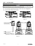
Page 21: ...2 Motor and brake voltages must be identical NOTE Brake control must be on separate circuit Diagram 11A Diagram 11B WARNING Typical schematics shown for motors that are reconnectable for high or low v...

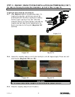
Page 22: ...wheels Refer to diagram 12A 12 2 The bracket has hole patterns as shown in Diagram 12B Bolt conductor bar hangers to brackets according to Diagram 12C 12 3 Each system requires the use of anchor clamp...

Page 23: ...h the first conductor bar Diagram 12G and tighten collector bolts to clamp it into place 12 7 Run a minimum of 4COND 12AWG SO W recommended cable from collectors to electrical enclosure as shown diagr...

Page 24: ...legs of the bar The conductor bar is furnished in lengths of 21 0 and the cover is furnished in lengths of 20 7 3 4 which allows 2 1 8 of the bar to extend beyond the cover at each end The cover fits...

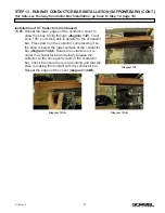
Page 25: ...ovided bolts through the near side bracket through the holes in the beam web and through the far side bracket securing brackets with lockwashers and hexnuts diagram 13D Note Bracket configuration show...

Page 26: ...ovided for them in the bracket diagrams 13E and 13F Make sure that the nibs are in the holes and the insulators are in the holes and the insulators are pressed firmly into the grooved parts of the SAF...

Page 27: ...upper opening of one bar Allow the conductor bars to go back together and slide the coupling bar half way into the adjoining bar so that it is centered over the joint diagrams 13H and 13J 13 8 Center...

Page 28: ...the coupling clamp diagram 13N 13 12 Place coupling cover over coupling clamp making sure the lips of the cover are firmly hooked over conductor bar legs diagram 13P 13 13 Replace insulating covers on...

Page 29: ...wedging them apart with a flat bladed screwdriver or similar allowing the clamp plate to slide into the upper slot diagram 13T Note If the tap is located close to a support the insulator mounting har...

Page 30: ...he heads For 2 2 conductor bar systems one collector is mounted near each wheel For 3 1 systems two collectors mount near one of the wheels The inner collector must ride in the inner conductor and the...

Page 31: ...ts long axis is parallel to the conductor bar Press down on the collector compressing it so the shoe is below the lower surface of the conductor bar diagram 13AA Rotate the collector so it is under th...

Page 32: ...ing the distance to the ceiling is not greater than 10 feet For distances greater than 10 feet additional points may need to be braced both laterally and longitudinally at the discretion of the end us...

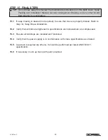
Page 33: ...led and functional 15 4 Verify that the power supply is in conformance with crane specifications as ordered 15 5 Load test is required by others It should be performed per latest ANSI B30 11 specifica...

Page 34: ...rong or apparently wrong the problem should be reported immediately to the proper supervisor and appropriate corrective action taken Operating Suggestions One measure of a good crane operator is the s...

Page 35: ...notice that dealer or distributor is not authorized to incur any obligations or to make any representations or warranties on Gorbel s behalf other than those specifically set forth in Gorbel s warran...

Page 36: ...This page intentionally left blank 32 9 18 Rev F...

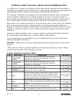
Page 37: ...should be off and locked when performing maintenance on any part of the system State and local codes may require inspection and maintenance checks more often Please check the state and local code man...

Page 38: ...te When lubricating through grease fitting or repacking suspension pins and ball joint rocker assembly should be raised approximately 1 4 Every 150 hours or 1 month 3 Wheels Guide Rollers Check for lo...

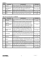
Page 39: ...sulators On type ST collectors check for free movement or pantograph Lubricate pivot pins as required Collector bracket tubes should be vertical within 1 16 Replace if necessary Every 750 hours or 4 m...

Page 40: ...t drives L A G M A 8 compound NOTE When above equipment is used outdoors we recommend a field change in oil in some cases as low as SAE 10 when cold weather arrives Consult local lubrication engineer...

Reviews: