4
9/18 Rev. F
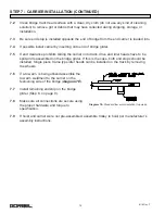
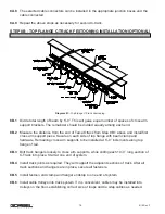
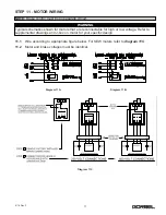
STEP 3 - HEADER WELDMENT INSTALLATION
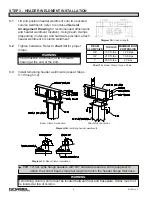
3.1
Lift and position header weldment onto two secured
column weldments (refer to enclosed
General
Arrangement Drawing
for recommended dimensions
and header weldment location). Using beam clamps
(depending on design) and hardware provided, attach
header weldment to column weldment.
3.2
Tighten hardware. Refer to
chart 3A
for proper
torque.
3.3
Install remaining header weldments (repeat Steps
3.1 through 3.2).
WARNING
There must be a minimum of two threads
showing at the end of the bolt.
Diagram 3B.
Installing header weldments.
Diagram 3A.
Header length.
Diagram 3C.
Beam Clamp Installation.
TIP:
10” tall, wide flange headers with 5/8” hardware require a shim (supplied) to
obtain the correct beam clamp tail length to match the header flange thickness.
WARNING
If shimming column, shim must be located between floor and baseplate. Shims must not
be located at top of column.
BEAM
CLAMP SIZE TORQUE
MINIMUM BOLT
PRETENSION
5/8”
109 ft.-lbs.
12.3 kips
3/4”
210 ft.-lbs.
19.8 kips
1”
355 ft.-lbs.
25 kips
Chart 3A.
Beam Clamp Torque Chart.
Direct Bolt Connection
Beam Clamp Connection


