12
10/12 Rev. E
STEP 7 - FRICTION BRAKE INSTALLATION (OPTIONAL) (CONTINUED)
Brake Caliper Installation (continued)
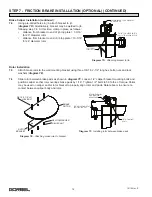
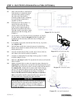
7.4
Using pre-drilled holes in jib, attach bracket to jib
(
diagram 7D
). Alternatively, bracket may be welded to jib
following step 7.6. At this time, clamp in place as follows:
• distance from bracket to end of jib top plate = 7-3/16”
for 20” diameter rotor
• distance from bracket to end of jib top plate = 10-3/16”
for 26” diameter rotor
Rotor Installation
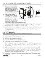
7.5
Attach brake rotor to the wall mounting bracket using three 3/8-16, 2-1/2” long hex bolts, nuts and lock
washers
(
diagram 7E
).
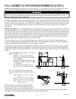
7.6
Slide rotor between brake pads as shown in
diagram 7F
. Loosen 1/2” caliper bracket mounting bolts and
position caliper so that rotor overlaps brake pads by 1/16”. Tighten 1/2” bolts to 50 ft.-lbs. of torque. Shims
may be used on caliper and/or rotor bracket to properly align rotor and pads. Rotate boom to ensure no
contact between caliper body and rotor.
10-3/16" FOR 30534 ROTOR
7-3/16" FOR 30520 ROTOR
FLAT WASHERS, LOCK WASHERS
AND HEX NUTS
1/2"-13 X 2"
LONG BOLTS
Diagram 7D.
Attaching bracket to jib.
ROTOR PARALLEL
AND BETWEEN
BRAKE PADS
5/8" MOUNTING BOLTS
(NOT INCLUDED)
1/2" MOUNTING
BOLTS
Diagram 7F.
Installing rotor between brake pads.
Diagram 7E.
Attaching brake rotor to bracket.
BRAKE
ROTOR
3/8 LOCKWASHER
ROTOR
BRACKET
3/8-16, 2 1/2” LG
HEX BOLT
3/8 HEX NUT

