13
10/12 Rev. E
STEP 7 - FRICTION BRAKE INSTALLATION (OPTIONAL) (CONTINUED)
Lever Bracket Installation
7.7
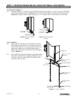
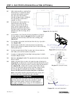
For beam depths 12” or less using rotor P/N 30520 and for beam depths 14” or less using rotor P/N 30534,
locate lever bracket as shown in
diagram 7G
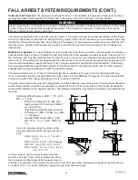
. For all other beam depths, locate lever bracket as shown in
diagram 7H
. Attach bracket to beam using 5/16” x 1-1/4” long hex bolts or weld brackets on both sides.
Lever Installation
7.8
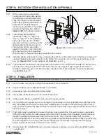
Attach cam to turnbuckle and to the bottom hole of the
lever weldment using 5/16-18, 1.25” long hex bolt and
lock nut. Use 5/16-18, 1.5” long hex bolt and lock nut to
attach lever weldment to the brake release bracket.
Attach pull chains to the lever weldment using hardware
show
in
diagram 7J
.
7.9
Use turnbuckle to adjust cable tension and brake release
lever action. When brake is properly adjusted it requires
a minimum of 40 lbs. of horizontal force applied at the
end of the boom to rotate.
5/16" x 1-1/4"
LONG HEX BOLTS
HANDLE BRACKET
P/N: 30555
Diagram 7G.
Lever bracket
location.
Diagram 7J.
Lever installation.
TURNBUCKLE
5/16-18, 1 1/2” LG
HEX BOLT
5/16-18, 1 1/4” LG
HEX BOLT
LEVER WELDMENT
S-HOOK
ENDWELDED
CHAIN
OPEN EYEBOLT,
1/4-20
ROUND KNOB
1/4-20 HEX NUT,
LOCKWASHER
CAM
5/16-18
LOCK NUT
5/16" X 1-1/4"
LONG HEX BOLTS
HANDLE BRACKET
P/N: 30557
Diagram 7H.
Lever bracket
location.

