14
10/12 Rev. E
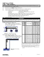
STEP 8 - DRIVE INSTALLATION (WALL MOUNTED) (OPTIONAL)
Holes must be drilled in wall column to mount
reducer assembly (refer to General Arrangement
Drawing for hole pattern, bolt size, and pattern
location). Spacer plates (when required) are
shipped loose.
8.1
The clutch is pre-tightened by Gorbel.
If any additional clutch adjustment is
required, refer to the friction clutch
instructions
below.
If the clutch is not
tightened properly, the lever arm may
slip and the Swing Arm may not rotate
properly.
8.2
Layout reducer mounting location on
support structure. Ensure that mounting
surface of support structure is plumb
along the plane comprising upper and
lower pivot mounts and drive mount.
Locate and drill holes.
8.3
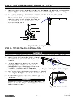
Install swing arm according to instructions in Step 2 on page 7 or Step 4 on page 10.
Hardware by others (grade 5 or better).
8.4
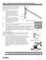
Lower drive assembly into place with lever arm engaged on pivot block and install
mounting hardware (grade 5 or better, by others) but do not tighten. Verify that the
drive is aligned with the axis of rotation of the swing arm and that there is
approximately a 1” gap between the bottom of the lever arm and the top plate of the
Swing Arm (
diagram 8B
). Torque drive mounting bolts (refer to
chart 8A
for proper
torque
rating).
Friction Clutch Installation
During normal operation, adjustment to compensate for friction lining wear may
be necessary. The frequency of these adjustments will be dependent on the
frequency of overloads occurring.
8.5
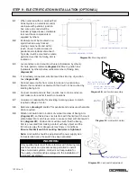
CLUTCH TORQUE ADJUSTMENT - SYSTEMS USED INDOORS
Loosen the locking screw on the adjusting nut. Using the hook wrench
provided, turn the adjusting nut counterclockwise until the drive
sprocket can turn freely in the clutch. The clutch can now be
retightened to the proper torque setting. Turn the adjusting nut
clockwise until it is hand tight. Using the hook wrench provided,
tighten the adjusting nut an additional two full revolutions. After the
adjustment is made, tighten the locking screw to ensure that the
adjusting nut doesn’t loosen. The proper torque setting is achieved when
the drive sprocket will not slip under
normal
operating conditions
(
diagram 8C
).
Diagram 8A.
Drive installation.
Bolt Dia.
Torque
1/2”
50 ft.-lbs.
5/8”
95 ft.-lbs.
3/4”
175 ft.-lbs.
7/8”
300 ft.-lbs.
1”
450 ft.-lbs.
Chart 8A.
Torque
ratings.
TIP:
The friction clutch is shipped
pretightened
by Gorbel. If the clutch begins to slip during initial use,
allow the clutch to slip several times then retighten the clutch per the instructions below. The purpose
for allowing the clutch to slip several times is to establish a uniform surface on the friction linings.
Diagram 8C.
Indoor clutch torque
adjustment.
Diagram 8B.
Drive clutch detail.

