FALL ARREST SYSTEM REQUIREMENTS (CONT.)
Horizontal Fall Clearance:
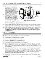
The Swing Arm, without the drive or friction brake, is designed to freely pivot so that a
small gently applied force will allow the Swing Arm to be slowly moved into a directly overhead position.
The freely pivoting Swing Arm will reduce impact forces on the worker through the inertial acceleration of the Swing
Arm for an offset from vertical fall. The Swing Arm may slowly rotate until an obstruction is encountered or the swing
reaches its rotation limit (Swing Arm’s full rotation is 210 degrees). If any dangerous obstructions are within the fall
clearance zone, optional rotation stops are required to limit the fall clearance zone and keep it free of dangerous
obstructions.
Multiple User Systems:
If a single Swing Arm is to be used by more than one worker, the Swing Arm must have an
optional friction brake or drive. In addition to this, only SRLs with extra available line shall be used. In the event of a
fall, the Swing Arm must be restricted from movement so as to prevent a second worker from being pulled off his/her
work surface. If the Swing Arm is equipped with the optional drive, it must be moved into the desired position and the
drive electrical enclosure properly locked out prior to anyone working at height and using this system. If the Swing
Arm is equipped with the optional friction brake, it must be moved into the desired position and the brake properly
engaged prior to anyone working at height and using the system.
The brake and drive rely on friction to hold the Swing Arm in position. In the event of a fall, the Swing Arm may
move to vertically align the activated lifeline and may rotate up to an additional 10 degrees. To reduce the potential
of a second worker from falling, extra payout line is required in the SRL.
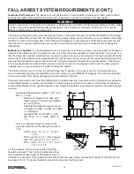
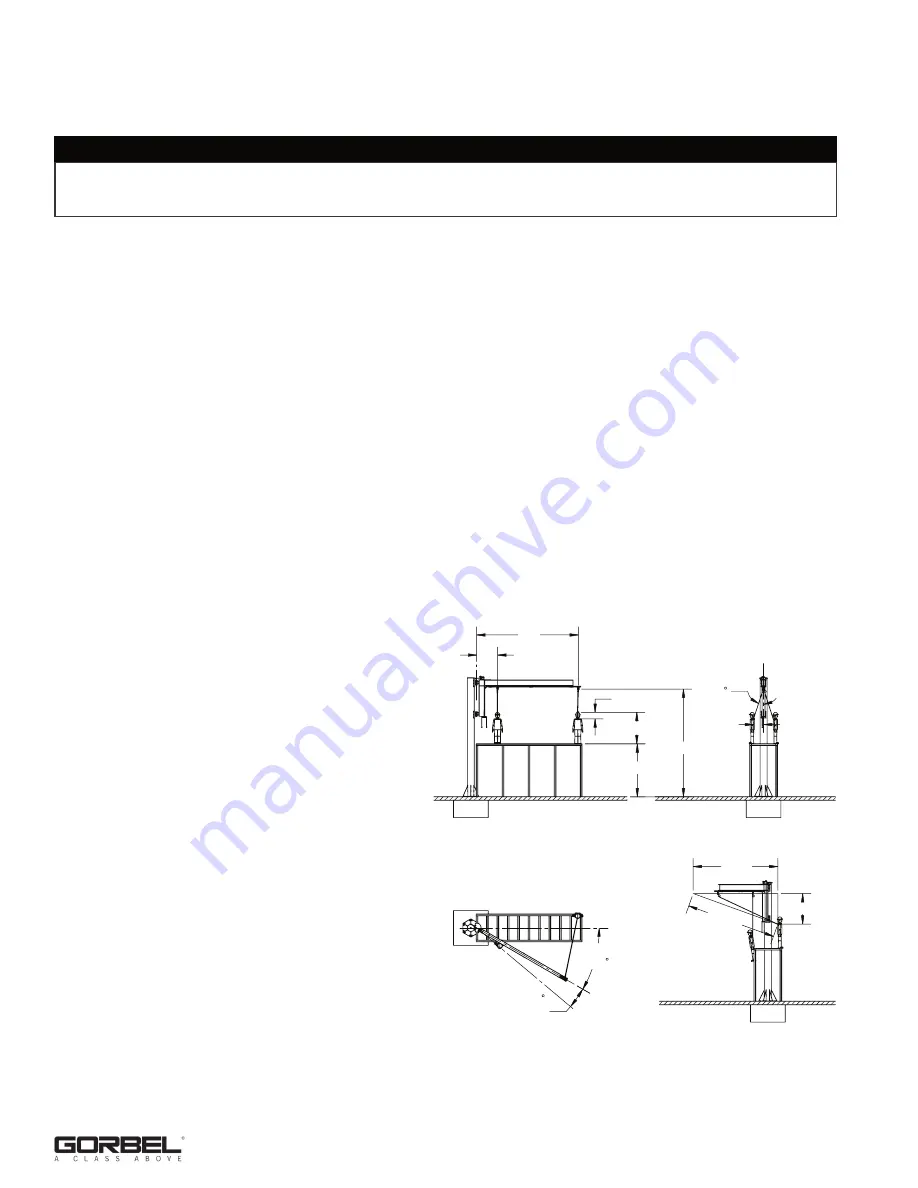
The worst case would occur when the falling worker is located near the pivot point and is at the maximum allowable
vertical offset distance, and the second worker is located at the end of the boom and is at the maximum allowable
vertical offset distance in the opposite direction. The following calculation is provided to determine the additional line
required.
Horizontal Offset Distance (HOD) = (TS - WS -
WH + 1) * sin
Ө
• Rotation of Swing Arm to align with
leading edge at 4 ft from pivot (RSA) =
arc tan (HOD/4)
• Possible Horizontal Movement at end
of Swing Arm (HM) = SPAN * tan (RSA
+ 10 degrees)
• Required SRL Length (RSL) = ((TS -
WS - WH + 1) ^2 + (HM + HOD) ^2)
^.5
Here’s an example using the values in the
previous example and the Swing Arm span is
20
ft.
HOD = (20.5 - 10 - 6 + 1) * sin 20 =
1.9
ft.
RSA = arc tan (1.9/4) = 25.4 degrees
HM = 20 * tan (25.4 + 10) = 14.2 ft.
RSL = ((20.5 - 10 - 6 + 1) ^2 + (14.2 +
1.9) ^.5 = 17 ft.
For this example, the maximum length of the SRL
should be at least 17 feet. Further restrictions (other
than a maximum offset angle of 20 degrees) may be
enforced. For example, if the workers must remain 6 feet from each other, the maximum length of the SRL should
be at least 10.5 ft. It is recommended to remain directly under the Swing Arm.
18
10/12 Rev. E
WARNING
Sudden movements or hard pulls on the lanyard or lifeline must be avoided. For Swing Arms without a friction brake
or drive, a large force applied horizontally perpendicular to the Swing Arm will create inertia forces that may be
difficult to resist and may cause a fall event.
WS = 10'
TS = 20.5'
WH = 6'
1'
4'
20'
20
1.9'
HOD =
5.5'
16.1'
17'
RSL =
25.4
RSA =
MARGIN
ADD 10
SAFETY

