background image

INSTRUCCIONES DE ENSAMBLAJE

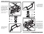
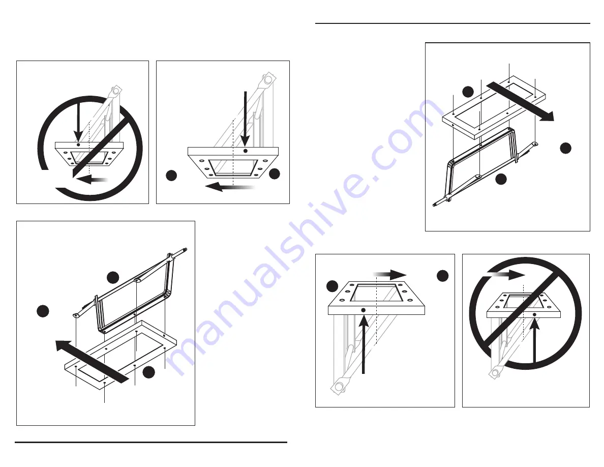
Fig. 5

Fig. 6

4.  El ensamble del eje 

posterior (E) se fija a la 

sección posterior de la 

estructura posterior (D).  

Revise dos veces la 

ubicación de la estructura 

posterior (D) antes de 

ensamblarla en el tubo.  

Los orificios laterales de 

la estructura posterior (D) 

deben estar mirando 

hacia la parte posterior 

de la bandeja (A).  

Consulte las etiquetas 

delantera y posterior en 

la parte posterior de la 

estructura posterior (D) 

para confirmar que la 

ubicación está correcta, 

como se muestra en las 

figuras 4, 5 y 6.

NOTA:  Si la estructura posterior (D) no está instalada correctamente, como 

se muestra en la Fig. 6, la instalación del ensamble del seguro del 

porta-basura (B) en el paso 6 no se enganchará cuando la bandeja del carrito 

(A) esté hacia abajo.

5

EL ORIFICIO LATER

AL 

FRENTE AL CENTRO EST

Á 

Cen

ter

Line

Cen

tro

EL FRENTE 

DE LA 

BANDE

JA

CORREC

TO

EL ORIFICIO LATER

AL 

DETR

ÁS DEL CENTRO EST

Á 

Cen

ter

Line

Cen

tro

INCORREC

TO

Fig. 4

EL FRENTE 

DE LA B

ANDEJA

D

A

A

D

E

EL FRENTE 

DE LA 

BANDE

JA

ASSEMBLY INSTRUCTIONS

Fig. 5

Fig. 6

4.  The rear axle assembly (E) 

attaches to the rear section of 

the rear frame (D). 

Double check the rear frame 

(D) placement before 

assembling to the tub. The 

side holes on the rear frame 

(D) must be towards the rear of 

the tray (A).  Please reference 

the front and rear labels on the 

backside of the rear frame (D) 

to confirm correct placement, 

as shown in Fig. 4, 5 and 6.

NOTE:  If the rear frame (D) is installed incorrectly, as shown in Fig. 6, the dump 

lock assembly (B) installation in Step 6 will not engage when the cart tray (A) is 

in the down position.

5

SIDE HOLE IN REAR

OF CENTER IS 

Center

Line

Center

FRONT

OF TRAY

CORRECT

SIDE HOLE IN FRONT

OF CENTER IS 

Center

Line

Center

FRONT

OF TRAY

INCORRECT

Fig. 4

FRONT

OF TRAY

D

A

A

D

E

Summary of Contents for GOR2540D

Page 1: ... our customer service department at 1 800 867 6763 9 a m 4 p m CST Monday Friday Preguntas sobre el producto Tricam 7677 Equitable Drive Eden Prairie MN 55344 800 867 6763 www gorillacarts com Instrucciones Importantes de Seguridad Instrucciones de Ensamblaje Información de Piezas y Herrajes PRECAUCIÓN Leer entender y seguir TODAS las instrucciones antes de usar este producto ADVERTENCIA No usar p...

Page 2: ......

Page 3: ...rontal 1 Rueda 4 Manija 1 Kit de aditamentos 1 A B C D E F G H I J K 1 CONTENIDO DEL PAQUETE consulte la sección Aditamentos para obtener más detalles A B C C D E F G H I I I I J K PACKAGE CONTENTS Part Description Quantity Tray 1 Dump Lock Assembly 1 Rear Strut 2 Rear Frame 1 Rear Axle Assembly 1 Front Frame 1 Front Strut 2 Front Axle Assembly 1 15 Tire 4 Handle 1 Hardware Kit see Hardware Conten...

Page 4: ...d Imagen Pieza Descripción Cantidad Imagen Pieza Descripción Llave allen Las imágenes no están a escala 4 CC M8 x 35mm Perno cabeza de hongo EE M8 x 20mm Perno cabeza de botón interna 2 HARDWARE CONTENTS WARNINGS AND CAUTIONS READ ALL INSTRUCTIONS BEFORE USE If you do not understand these instructions need further clarification or further explanation please call our toll free answer line at 1 800 ...

Page 5: ...bles No se incluyen las herramientas 3 DD x 4 Arandela plana M8 KK Contratuerca M8 x 4 M8 x 20mm Perno cabeza de hongo x 4 MM Contratuerca M6 x 2 NN Arandela plana M6 x 2 GG x 2 M6 x 16 Perno de hombro FF F H DD KK NN MM GG FF ASSEMBLY INSTRUCTIONS Fig 1 Hardware Used Note During each step of assembly assemble all hardware and hand tighten Once all the hardware is installed for that particular ste...

Page 6: ... Aditamentos utilizados Fig 3 DD x 4 Arandela plana M8 KK Contratuerca M8 x 4 M8 x 20mm Perno cabeza de hongo x 4 GG C C E G G H F DD DD DD KK KK GG GG ASSEMBLY INSTRUCTIONS Fig 2 Hardware Used 2 Attach the front struts G to connect the the front axle assembly H to the front frame F using four M8 x 20mm carriage bolts DD using four M8 lock nuts KK and four M8 washers GG as shown in Fig 2 Tighten a...

Page 7: ...IO LATERAL FRENTE AL CENTRO ESTÁ Center Line Centro EL FRENTE DE LA BANDEJA CORRECTO EL ORIFICIO LATERAL DETRÁS DEL CENTRO ESTÁ Center Line Centro INCORRECTO Fig 4 EL FRENTE DE LA BANDEJA D A A D E EL FRENTE DE LA BANDEJA ASSEMBLY INSTRUCTIONS Fig 5 Fig 6 4 The rear axle assembly E attaches to the rear section of the rear frame D Double check the rear frame D placement before assembling to the tub...

Page 8: ...ción esta correcto El frente de la bandeja M8 x 20mm pernos cabeza de hongo x 5 x 1 x 6 M8 x 25mm pernos cabeza de hongo Arandela plana M8 CC BB GG A D E KK CC HH BB GG x 6 KK Contratuerca M8 x 6 HH Arandela plana M11 ASSEMBLY INSTRUCTIONS Fig 7 Hardware Used 5 Attach the rear axle assembly E with the rear struts C and the rear frame D to the tray A using five M8 x 38 carriage bolts BB one M8 x 35...

Page 9: ...posterior D en el paso 4 M8 x 20mm pernos cabeza de hongo M8 x 20mm Perno cabeza de botón interna KK GG EE KK GG CC x 3 HH Arandela plana M11 D F EE EE GG KK A B GG CC HH KK ASSEMBLY INSTRUCTIONS Fig 8 Hardware Used 6 Attach the rear frame D to the front frame F using two M8 x 20mm internal button head bolts EE two M8 lock nuts KK and two M8 washers GG as shown in Fig 8 7 x 2 x 2 M8 Flat Washer KK...

Page 10: ...I JJ LL Fig 10 I II JJ LL Fig 11 Aditamentos utilizados X 1 M8 x 60mm Perno cabeza de botón interna x 1 x 1 Arandela plana M8 Contratuerca M8 AA KK GG ASSEMBLY INSTRUCTIONS 8 Fig 10 Hardware Used 8 Attach the four wheels I by first placing the wheel spacers II onto each axle then the wheels I and M12 flat washers JJ and M12 lock nuts LL as shown in Fig 10 I X 4 Wheel Spacer II II JJ JJ M12 Flat Wa...

Page 11: ... 3 9 Fig 2 Fig 3 Fig 1 Fig 2 Fig 3 Fig 1 INSTRUCCIONES DE OPERACIÓN 1 PARA UTILIZAR LA CARACTERÍSTICA DE VOLCADO Para utilizar la característica de volcado jale la manija de liberación de volcado hacia delante para liberar la bandeja del mecanismo de bloqueo Levante la manija de liberación para girar la bandeja hacia arriba a la posición de volcado como se muestra en la Fig 2 PARA UTILIZAR LA MANI...

Page 12: ...3 9 a m 4 p m CST Monday Friday B C D E F G H I I I I J K LISTA DE PIEZAS DE REPUESTO 10 INSTRUCCIONES DE OPERACIÓN BOLSILLOS LATERALES Para incrementar los pies cúbicos de este artículo estos 8 bolsillos pueden utilizarse en los paneles laterales como se muestra Estos bolsillos eal dimensionada de 1 9cm x 6 35cm como se muestra en la Fig 1 Fig 1 Pieza Descripción Cantidad Ensamble del seguro del ...

Reviews: